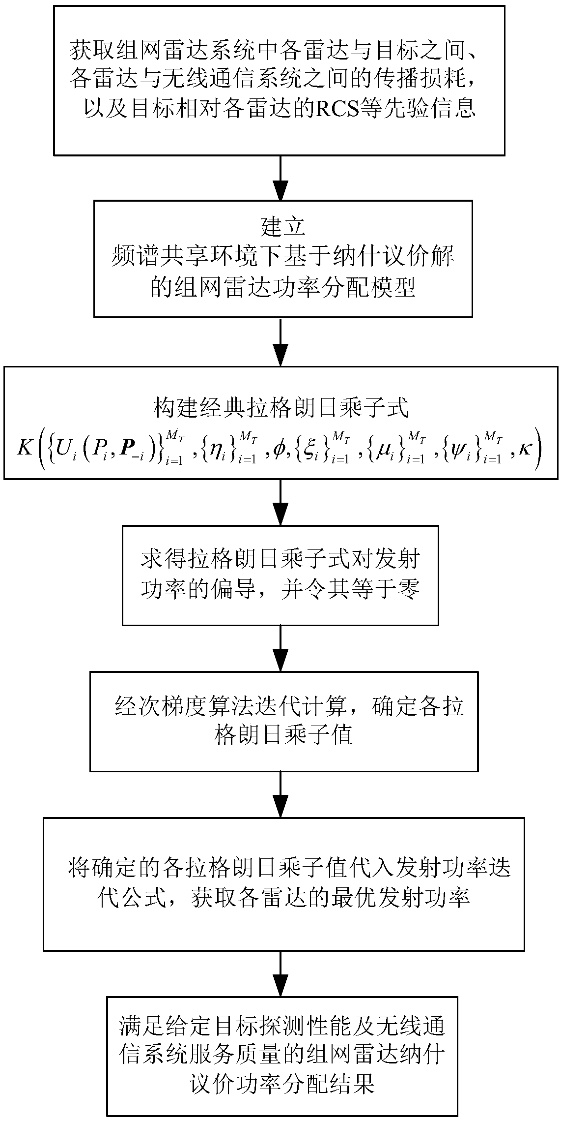
Nash-bargaining-solution-based networked radar power allocation method in spectrum coexistence environment

A networked radar and Nash bargaining technology, applied in power management, wireless communication, electrical components, etc., can solve the problems of lack of networked radar, spectrum coexistence between networked radar and wireless communication system, interference of wireless communication services, etc. Achieve the effect of meeting the spectrum coexistence

Inactive Publication Date: 2018-11-16
NANJING UNIV OF AERONAUTICS & ASTRONAUTICS
View PDF2 Cites 4 Cited by
  • Summary
  • Abstract
  • Description
  • Claims
  • Application Information

AI Technical Summary

Problems solved by technology

[0005] At present, the existing methods have proposed the power allocation of non-cooperative game networking radar based on radio frequency stealth and the idea of ​​power allocation of cooperative game networking radar based on radio frequency stealth, which improves the radio frequency stealth performance of the networked radar system, but none of the existing methods considers In the actual battlefield environment, the spectrum coexistence of networked radars and wireless communication systems does not take into account the harmful interference caused by each radar in the system to the communication system
However, in practical engineering applications, as the wireless spectrum is continuously allocated to various radio frequency equipment, the networked radar and the wireless communication system often coexist in the same frequency band, and the high transmission power of each radar in the networked radar system will affect the Wireless communication services have a large impact, so it needs to be considered in the transmission power allocation
[0006] In summary, there is a lack of a networked radar power allocation method in the prior art, which minimizes the transmission power of the networked radar and avoids excessive interference to wireless communication services caused by the high transmission power of the networked radar.

Method used


Image

  • Nash-bargaining-solution-based networked radar power allocation method in spectrum coexistence environment
  • Nash-bargaining-solution-based networked radar power allocation method in spectrum coexistence environment
  • Nash-bargaining-solution-based networked radar power allocation method in spectrum coexistence environment

Examples


Embodiment 1

[0094] The geometric position relationship between networked radar, wireless communication system and target is as follows: image 3 As shown, the RCS model is That is to say, the RCS of the target relative to each radar viewing angle is equal.

Embodiment 2

[0096] The geometric position relationship between networked radar, wireless communication system and target is as follows: image 3 As shown, the target RCS model is That is to say, the RCS of the target relative to each radar viewing angle is not equal.

Embodiment 3

[0098] The geometric position relationship between networked radar, wireless communication system and target is as follows: Figure 4 As shown, the RCS model is


PUM


Abstract

The invention, which relates to the field of radar signal processing, discloses a Nash-bargaining-solution-based networked radar power allocation method in a spectrum coexistence environment. The method comprises: determining channel propagation losses between all radars and a target in a networked radar system and channel propagation losses between all radars and a communication system as prioriinformation; determining a target detection SINR threshold and a communication system maximum tolerant interference power threshold; establishing a Nash-bargaining-solution-based networked radar powerallocation model in a spectrum coexistence environment; and calculating the networked radar power allocation model to obtain allocation results, and selecting an optimal solution enabling transmitting powers of all radars to be minimized from the allocation results. According to the invention, the radio frequency stealth performance of the networked radar power distribution network radar system can be optimized and the high transmission power of the networked radar is kept to be within the maximum tolerable interference power of the communication system, so that the interference on the communication system by the networked radar is eliminated.

Description

technical field [0001] The invention relates to the field of radar signal processing, in particular to a method for allocating networked radar power based on Nash bargaining solutions in a spectrum coexistence environment. Background technique [0002] In recent years, with the rapid development of wireless communication hardware and software technology, wireless spectrum resources have been continuously allocated to various radio frequency systems, resulting in fewer and fewer available frequency bands, and wireless spectrum resources have become increasingly scarce. resource. The traditional method to solve the spectrum congestion of radar and wireless communication system is to separate the operating frequency bands of the two to avoid interference to each other. However, in the face of the sharp increase in the number of wireless radio frequency equipment on the battlefield and the increasing expansion of operating bandwidth, traditional methods have become increasingly...

Claims


Application Information

Patent Timeline
Patent Type & Authority Applications(China)
IPC IPC(8): H04W52/14H04W52/24
CPCH04W52/146H04W52/242H04W52/243
Inventor 时晨光汪飞李海林周建江夏伟杰孔莹莹
Owner NANJING UNIV OF AERONAUTICS & ASTRONAUTICS
Why Eureka
Try Eureka