Charge-discharge balance converter for uninterruptible power supply

A balancing converter, charging and discharging technology, applied in collectors, emergency power arrangement, battery load switching, etc., can solve the problems of increasing the cost and volume of uninterruptible power supply 1, achieve low cost, suppress ripple current and ripple The effect of voltage and small size

Active Publication Date: 2022-06-03
EATON INTELLIGENT POWER LTD
View PDF3 Cites 0 Cited by
  • Summary
  • Abstract
  • Description
  • Claims
  • Application Information

AI Technical Summary

Problems solved by technology

This instead increases the cost and size of the UPS 1

Method used


Image

  • Charge-discharge balance converter for uninterruptible power supply
  • Charge-discharge balance converter for uninterruptible power supply
  • Charge-discharge balance converter for uninterruptible power supply

Examples


Embodiment Construction

[0032] In order to make the objectives, technical solutions and advantages of the present invention clearer, the present invention will be further described in detail below with reference to the accompanying drawings through specific embodiments.

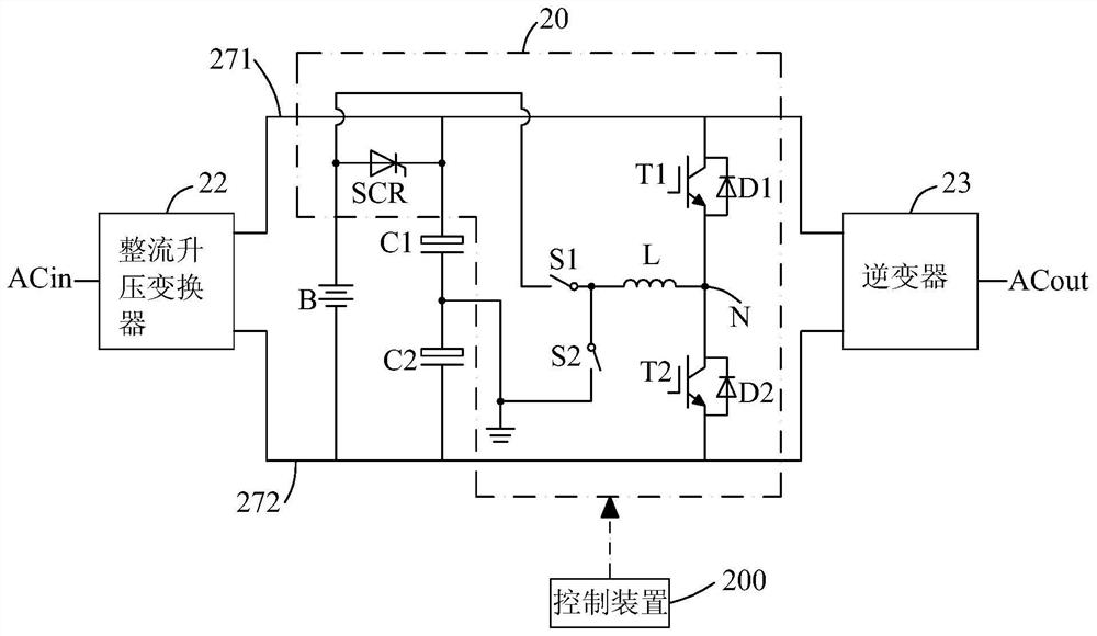
[0033] figure 2 It is a circuit diagram of a charge-discharge balancing converter for an uninterruptible power supply according to the first embodiment of the present invention. like figure 2 As shown, the charge-discharge balancing converter 20 includes an insulated gate bipolar transistor (IGBT) T1 having an anti-parallel diode D1, an IGBT T2 having an anti-parallel diode D2, an inductor L, a first switch S1, a second Switch S2 and thyristor SCR. The IGBT T1 and the IGBT T2 are sequentially connected between the positive DC bus 271 and the negative DC bus 272, and the IGBT T1 and the IGBT T2 are connected to form a node N. One end of the inductor L is connected to the node N, the other end of the inductor L is connected to th...


PUM


Abstract

The present invention provides a charge-discharge balance converter for an uninterruptible power supply. The uninterruptible power supply includes a positive DC bus, a negative DC bus, a first capacitor and a second capacitor, wherein the charge-discharge balance converter includes: a first switch tube with anti-parallel diodes and a second switch tube with anti-parallel diodes, the first switch tube and the second switch tube are sequentially connected between the positive DC bus and the negative DC bus; connected to form a node: an inductor, a first switch and a controllable unidirectional conductive device, one end of the inductor is connected to the node, and the other end of the inductor is connected to the controllable unidirectional conductive device through the first switch in turn to the positive DC bus; and a second switch connected between the other end of the inductor and an intermediate node formed by connecting the first capacitor and the second capacitor. The charge-discharge balance converter of the present invention has few components, small volume and low cost.

Description

technical field [0001] The invention relates to electronic circuits, in particular to a charge-discharge balancing converter for uninterruptible power supplies. Background technique [0002] Uninterruptible power supplies can continuously supply power to loads and have been widely used in various fields. [0003] figure 1 It is a block diagram of an uninterruptible power supply in the prior art. like figure 1 As shown, the bypass input terminal Bin is connected to the AC output terminal ACout through the static transfer switch 11, the mains input terminal ACin is connected to the AC output terminal ACout through the rectifier boost converter 12 and the inverter 13 in turn, and the rechargeable battery 14 is connected through The DC / DC converter 15 is connected to the positive DC bus 171 and the negative DC bus 172 , and the charger 16 can charge the rechargeable battery 14 with the electric energy on the positive DC bus 171 and the negative DC bus 172 . The uninterruptib...

Claims


Application Information

Patent Timeline
Patent Type & Authority Patents(China)
IPC IPC(8): H02J9/06H02J7/00
CPCH02J7/0068H02J9/062
Inventor 李化良徐忠勇欧阳华奋袁沛华
Owner EATON INTELLIGENT POWER LTD
Why Eureka
Try Eureka