
Azimuth imaging method based on MIMO rectangular plane array

An imaging method and a planar array technology, which are applied in the reflection/re-radiation of radio waves, the use of re-radiation, and measurement devices, etc., can solve the problems of complex system configuration, low algorithm calculation efficiency, and high algorithm operation efficiency, and achieve spectral information improvement. Effect

Active Publication Date: 2018-11-16
INST OF ELECTRONICS CHINESE ACAD OF SCI
View PDF5 Cites 7 Cited by
  • Summary
  • Abstract
  • Description
  • Claims
  • Application Information

AI Technical Summary

Problems solved by technology

[0004] The traditional back-projection method selects dense back-projection points on the imaging surface, so it has better azimuth resolution but also has a large amount of calculation, resulting in low calculation efficiency of the algorithm; while the frequency-wavenumber domain algorithm uses Fourier Leaf transformation processes scattered echo data, and the algorithm has high operation efficiency, but it has high sampling requirements for receiving antennas and transmitting antennas, resulting in complex system configuration and high cost

Method used


Image

  • Azimuth imaging method based on MIMO rectangular plane array
  • Azimuth imaging method based on MIMO rectangular plane array
  • Azimuth imaging method based on MIMO rectangular plane array

Examples


Embodiment Construction

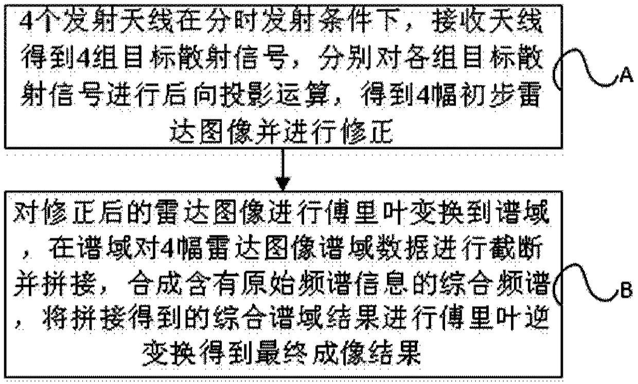
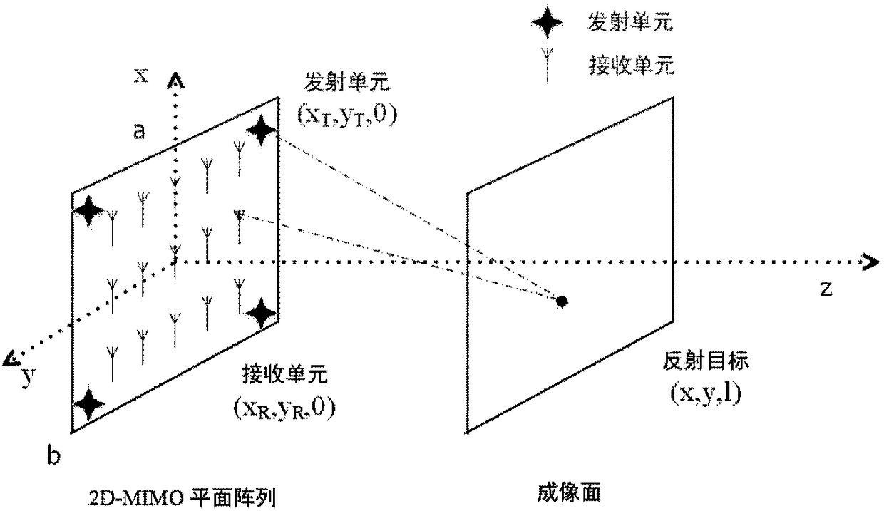
[0056] The present disclosure provides an azimuth imaging method based on a MIMO rectangular planar array, including step A and step B, wherein step A: under the condition of time-sharing transmission by four transmitting antennas, the receiving antennas obtain four groups of target scattering signals, respectively Each group of target scattering signals is back-projected to obtain 4 preliminary radar images and correct them; Step B: Fourier transform the corrected radar images into the spectral domain, and compare the spectral domain data of the 4 radar images in the spectral domain Carry out truncation and splicing, and inverse Fourier transform the integrated spectral domain results obtained by splicing to obtain the final imaging result. This disclosure effectively solves the relationship between the length of the MIMO array, the number of array elements and the azimuth resolution under the topology structure of a specific sparse rectangular planar MIMO array, and at the sa...


PUM


Abstract

The invention provides an azimuth imaging method based on a MIMO rectangular plane array. The method includes a step A of performing backward projection operation on each of four groups of target scattered signals obtained by a receiving antenna when four transmitting antennas are in a time-share transmission condition, obtaining four preliminary radar images and performing modification; a step Bof performing Fourier transform on the modified radar images to a spectral domain, performing truncation and mergence on spectral domain data of the four radar images in the spectral domain and performing Fourier inversion on a comprehensive spectral domain result obtained through mergence and obtaining a final imaging result. The invention effectively solves a problem of the relationship among MIMO array length, array element number and azimuth resolution under the topological structure of the specific sparse rectangular plane MIMO array, and simultaneously gives attention to the operation efficiency. Truncation and mergence are performed on image data in the spectral domain, so that frequency spectrum information of a target is improved and imaging quality is improved. Besides, the computational efficiency is improved and the algorithm real-time performance is ensured by using Fourier transform.

Description

technical field [0001] The present disclosure relates to the technical field of MIMO planar array imaging signal processing, and in particular to an azimuth imaging method based on MIMO rectangular planar array for microwave frequency band. Background technique [0002] The imaging method is an important link in the MIMO array imaging process. The accuracy and timeliness of the imaging method largely determine the quality and efficiency of the imaging results. [0003] In the design of imaging methods based on MIMO planar arrays in the microwave band, it is mainly to effectively solve the relationship between the length of the MIMO array, the number of array elements and the azimuth resolution under the specific sparse rectangular planar NIMO array topology, and At the same time take into account the operational efficiency. Commonly used imaging methods mainly include traditional back-projection algorithms and frequency-wavenumber domain algorithms. [0004] The traditiona...

Claims


Application Information

Patent Timeline
Patent Type & Authority Applications(China)
IPC IPC(8): G01S13/89
CPCG01S13/89
Inventor 吴世有王慧黄玲方广有
Owner INST OF ELECTRONICS CHINESE ACAD OF SCI
Learn More