
Variable-flow-path parallel flow heat exchanger

A parallel flow heat exchanger and process technology, applied in evaporators/condensers, lighting and heating equipment, refrigeration components, etc., can solve the problem of reduced air-conditioning energy consumption ratio, large refrigerant flow resistance, low heat exchanger efficiency, etc. problem, to achieve the effect of improving performance and optimizing distribution

Active Publication Date: 2018-11-16
CENTRAL SOUTH UNIVERSITY OF FORESTRY AND TECHNOLOGY +1
View PDF9 Cites 8 Cited by
  • Summary
  • Abstract
  • Description
  • Claims
  • Application Information

AI Technical Summary

Problems solved by technology

[0003] This kind of parallel flow heat exchanger with a fixed flow cannot be changed after the design is completed, and the flow of the heat exchanger is designed for specific working conditions, such as standard refrigeration working conditions, but there are various working conditions when the air conditioner is running. And the comfort air conditioner is used for cooling in summer and heating in winter. The outdoor condensing heat exchanger and the indoor evaporative heat exchanger are used for cooling. The outdoor evaporative heat exchanger and the indoor condensing heat exchanger are used for heating. The working conditions faced by air conditioner heat exchangers have changed greatly, resulting in extremely low efficiency of traditional heat exchangers when heating, and at the same time, the heat transfer efficiency of heat exchangers is low when they are far away from specific working conditions
At the same time, under the unreasonable heat exchange process, the refrigerant flow resistance is relatively large, resulting in unnecessary pressure drop, resulting in a decrease in the energy consumption ratio of the air conditioner

Method used


Image

  • Variable-flow-path parallel flow heat exchanger
  • Variable-flow-path parallel flow heat exchanger
  • Variable-flow-path parallel flow heat exchanger

Examples


Embodiment Construction

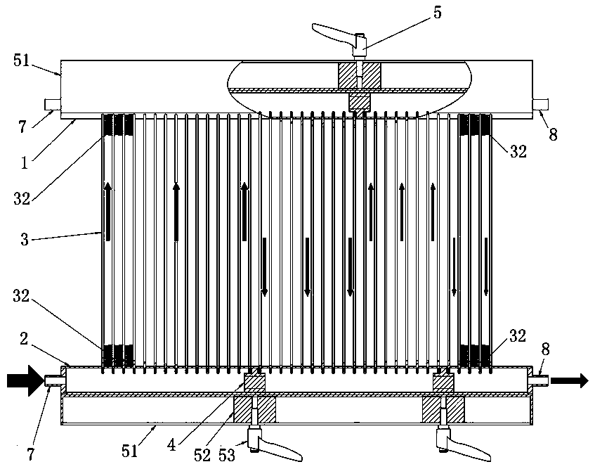
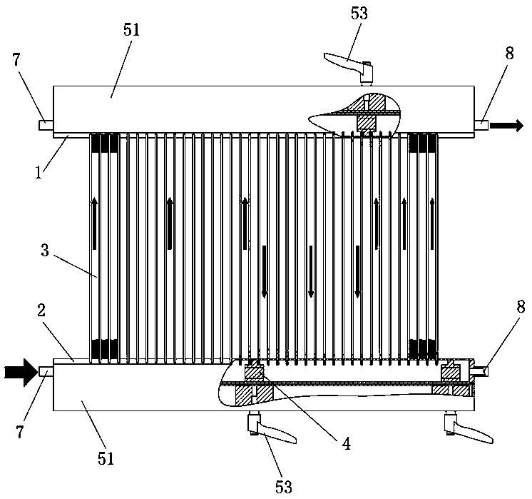
[0029] The present invention will be further described in detail below in conjunction with the accompanying drawings and specific embodiments.

[0030] Figure 1 to Figure 9 It shows an embodiment of the variable flow parallel flow heat exchanger of the present invention, including an upper header 1, a lower header 2 and an upper header 1 and a lower header 2 inserted between the header and the In the flat tube group 3 connected by the two, the upper header 1 and the lower header 2 are equipped with flow-blocking pistons 4 that can move in the axial direction, and the upper header 1 and the lower header 2 are equipped with There is an adjustment mechanism 5 for driving the corresponding blocking piston 4 to a predetermined position. In this structure, the refrigerant enters from the upper header 1 or the lower header 2, and conducts heat exchange through the flat tube group 3, and the position of the cooling flow isolation can be adjusted actively by the adjustment mechanism ...


PUM


Abstract

The invention discloses a variable-flow-path parallel flow heat exchanger which comprises an upper flow collecting pipe, a lower flow collecting pipe and a flat pipe set, wherein the flat pipe set ismounted between the upper flow collecting pipe and the lower flow collecting pipe in an inserted mode and communicates with the upper flow collecting pipe and the lower flow collecting pipe. The upperflow collecting pipe and the lower flow collecting pipe are both provided with flow isolating pistons capable of moving in the axial direction. The exteriors of the upper flow collecting pipe and thelower flow collecting pipe are both provided with adjusting mechanisms used for driving the corresponding flow isolating pistons to move to the predetermined positions. The variable-flow-path parallel flow heat exchanger has the advantages of being simple and reliable in structure, high in efficiency, and especially capable of being suitable for changed working conditions during working of an airconditioner.

Description

technical field [0001] The invention mainly relates to the technical field of heat exchangers, in particular to a variable flow parallel flow heat exchanger. Background technique [0002] At present, the parallel flow heat exchangers used in air conditioners are mainly fixed-flow heat exchangers, that is, the refrigerant is cut off by a fixed partition in the header, such as the header structure disclosed in the Chinese invention patent specification CN103047800A. A large number of literatures at home and abroad have conducted a lot of research on the selection of this heat exchanger process. [0003] This kind of parallel flow heat exchanger with a fixed flow cannot be changed after the design is completed, and the flow of the heat exchanger is designed for specific working conditions, such as standard refrigeration working conditions, but there are various working conditions when the air conditioner is running. And the comfort air conditioner is used for cooling in summer...

Claims


Application Information

Patent Timeline
IPC IPC(8): F25B39/00
CPCF25B39/00
Inventor 罗武生谢天磊廖曙光喻胜飞赵鹏朱雄晏
Owner CENTRAL SOUTH UNIVERSITY OF FORESTRY AND TECHNOLOGY
Learn More