Gear with pitted end face

A technology of gears and pits, applied in the direction of elements with teeth, belts/chains/gears, gear lubrication/cooling, etc., can solve the problems of tooth heel fracture, gear deformation, vibration increase, etc., to reduce gear temperature, The effect of reducing weight and reducing air resistance

Inactive Publication Date: 2018-11-16
柯尼齿轮箱(大连)有限公司
View PDF0 Cites 0 Cited by
  • Summary
  • Abstract
  • Description
  • Claims
  • Application Information

AI Technical Summary

Problems solved by technology

At the same time of meshing, a large amount of heat will be generated. If the temperature of the meshing gear pair cannot be lowered in time, the gears will be deformed, resulting in increased vibration, which will further deteriorate and eventually cause tooth surface gluing or even tooth heel fracture.

Method used


Image

  • Gear with pitted end face
  • Gear with pitted end face
  • Gear with pitted end face

Examples


Embodiment Construction

[0015] The present invention will be described in further detail below: the present embodiment is implemented on the premise of the technical solution of the present invention, and detailed implementation is provided, but the protection scope of the present invention is not limited to the following examples.

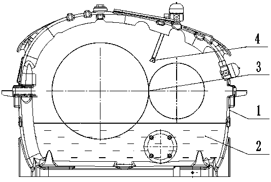
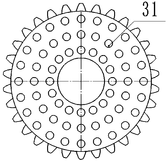
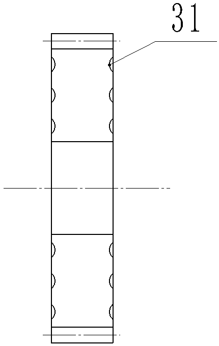
[0016] like Figure 1-3 As shown, for a gear with dimples on the end face, gear surface dimples 31 are provided on the surface of the gear pair 3;

[0017] The lubricating oil 2 is arranged in the reducer housing 1 , the gear pair 3 is submerged in the lubricating oil 2 , and the lubricating oil 2 is sprayed onto the gear pair 3 through the lubricating oil nozzle 4 .

[0018] The gear surface pits 31 are evenly distributed on the gear pair 3 in a circumferential shape, the diameter of the gear surface pits 31 is 10-50mm, and the depth is 2-5mm.

[0019] The above are only preferred specific implementations of the present invention. These specific implementations are all...


PUM


Abstract

The invention relates to a gear with a pitted end face. The surface of a gear pair is provided with gear surface pits, lubricating oil is arranged in a speed reducer housing, the gear pair is immersedin the lubricating oil, and the lubricating oil is sprayed to the gear pair through a lubricating oil jet nozzle. The gear with the pitted end face can improve the heat exchange efficiency, the temperature of the gear is reduced, the meshing effect is improved, the weight reduction is facilitated, in the high-speed rotation process of the gear, the gear with the pits is beneficial for reducing air resistance, the heat exchange area of the lubricating oil is increased, and the temperature reduction effect is obvious.

Description

technical field [0001] The invention relates to the field of mechanical processing and manufacturing, and is applied to reducer mechanical equipment, in particular to a gear with dimples on the end face. Background technique [0002] The reducer is a device used to reduce the speed and increase the torque. It is an important part of the power system, a key device, and occupies an important position in the entire power plant. The reducer itself is a device with rotating parts. The rotating part is the rotating shaft. The smooth operation of the rotating shaft is very important for the reducer. There are gears installed on the rotating shaft. Different gears are installed on different rotating shafts and mesh with each other to form gears. Yes, it has a certain speed ratio, so as to achieve the effect of decelerating and increasing torque. At the same time of meshing, a large amount of heat will be generated. If the temperature of the meshing gear pair cannot be lowered in t...

Claims


Application Information

Patent Timeline
Patent Type & Authority Applications(China)
IPC IPC(8): F16H55/17F16H57/04
CPCF16H55/17F16H57/0427
Inventor 徐德忠高世龙姜天辰林绪坤汤颖宋玉芸
Owner 柯尼齿轮箱(大连)有限公司
Why Eureka
Try Eureka