
Abrasion-resisting cutting tooth with damping function

A wear-resistant and functional technology, applied in the field of picks, can solve the problems of low cutting efficiency, scrapped picks, increased mining costs, etc., to achieve the effect of improving cutting efficiency, avoiding overall wear, and increasing the cutting area

Inactive Publication Date: 2018-11-16
许国梁
View PDF0 Cites 7 Cited by
  • Summary
  • Abstract
  • Description
  • Claims
  • Application Information

AI Technical Summary

Problems solved by technology

[0003] 1. When the pick is in contact with the rock formation, it will produce a severe impact. This impact force will directly act on the tooth shank and the tooth seat of the pick without buffering. In severe cases, the tooth shank will be bent Deformation, and then scrapping, increases the consumption of picks and increases the cost of mining;
[0004] 2. The composition of the pick is generally divided into three parts, the tooth seat, the tapered tooth shank and the wear-resistant head. The wear-resistant head and the tapered tooth shank are inlaid structures. There is no protective measure for the entire tapered tooth shank in contact with the rock formation. Therefore, serious wear and tear will occur, and the entire pick will be scrapped;
[0005] 3. When the wear-resistant head on the pick is in contact with the rock formation, the cutting area is small and the cutting efficiency is low

Method used


Image

  • Abrasion-resisting cutting tooth with damping function
  • Abrasion-resisting cutting tooth with damping function
  • Abrasion-resisting cutting tooth with damping function

Examples


Embodiment Construction

[0026] The following will clearly and completely describe the technical solutions in the embodiments of the present invention with reference to the accompanying drawings in the embodiments of the present invention. Obviously, the described embodiments are only some, not all, embodiments of the present invention. Based on the embodiments of the present invention, all other embodiments obtained by persons of ordinary skill in the art without making creative efforts belong to the protection scope of the present invention.

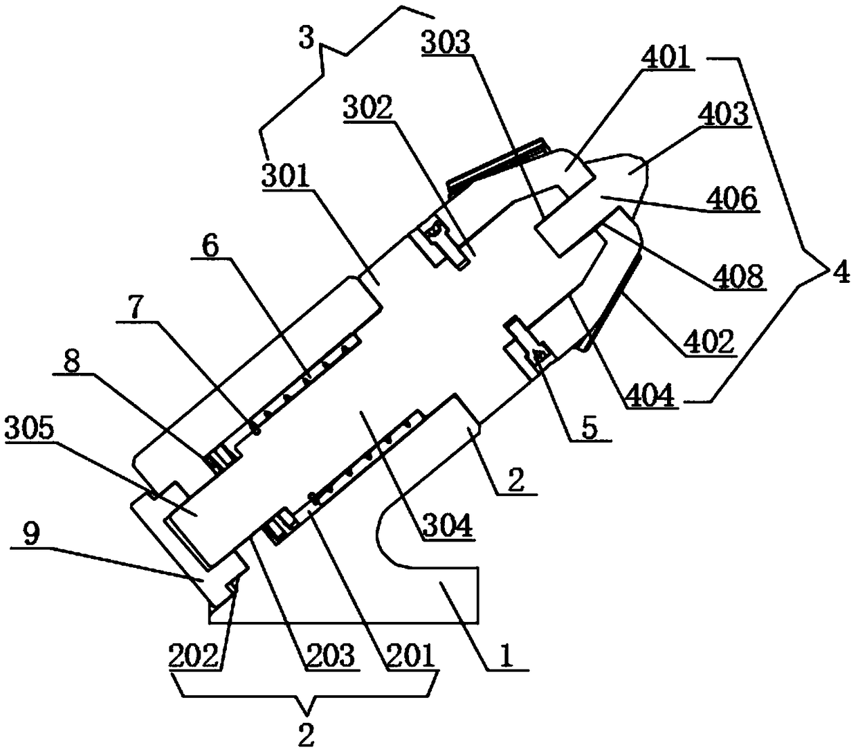
[0027] see Figure 1-6 , the present invention provides a technical solution: a wear-resistant pick with a shock-absorbing function, including a cutting seat, a mandrel body 3 set on the upper end of the cutting seat, and a pick head matched with the upper end of the mandrel body 3 4. The main body of the cutting seat is composed of an integrally formed plate-shaped connection base 1 and a cylindrical sleeve seat 2 with an inclined upper end of the connection ...


PUM


Abstract

The invention discloses an abrasion-resisting cutting tooth with a damping function. The abrasion-resisting cutting tooth comprises a cutting seat, a core shaft body arranged at the upper end of the cutting seat, and a cutting tooth head matched with the upper end of the core shaft body to be mounted. A main body of the cutting seat is composed of a connecting base of an integrally-formed platy structure and a sleeve seat which is obliquely arranged at the upper end of the connecting base and is of a cylindrical structure. When the cutting tooth head and the core shaft body make contact with arock stratum, generated instant high impact force is buffered and absorbed through a strong spring arranged at the lower end of the core shaft body in a sleeving mode and is downwards released to thecutting tooth head connected with the cutting seat. When the whole cutting tooth makes contact with the rock stratum, the first contact part is a main tooth body, second contact parts are a vice tooth body and a vice tooth sleeve on the cutting tooth head, and thus abrasion to the core shaft body on the cutting tooth due to excessive contact with the rock stratum is avoided; the main tooth body is arranged at the front end of the cutting tooth head, and the vice tooth body is arranged on the outer circle of the cutting tooth head; and when the cutting tooth makes contact with the rock stratum, the main tooth body and the vice tooth body making contact with the rock stratum cut the rock stratum simultaneously, the whole cutting area of the cutting tooth is increased, and the cutting efficiency is improved.

Description

technical field [0001] The invention relates to the technical field of mechanical accessories, in particular to a wear-resistant pick with a shock-absorbing function. Background technique [0002] Roadheaders and shearers are common important mining equipment, and picks are widely concerned as important cutting accessories on roadheaders and shearers, because the rock formations under the mine have high cutting strength, making the picks as a It is used as a fragile standing accessory, but it still has the following disadvantages in actual use: [0003] 1. When the pick is in contact with the rock formation, it will produce a severe impact. This impact force will directly act on the tooth shank and the tooth seat of the pick without buffering, and in severe cases, the tooth shank will be bent. Deformation, and then scrapping, increases the consumption of picks and increases the cost of mining; [0004] 2. The composition of the pick is generally divided into three parts, t...

Claims


Application Information

Patent Timeline
Patent Type & Authority Applications(China)
IPC IPC(8): E21C35/18E21C35/19
CPCE21C35/18E21C35/19
Inventor 许国梁施继良陈志霖
Owner 许国梁
Learn More