Sewage treatment device based on electrolytic flotation

A sewage treatment device and electrolytic air flotation technology, which can be used in flotation water/sewage treatment, water/sewage treatment, water/sludge/sewage treatment, etc., and can solve the problem of prolonging electrolysis time, reducing electrolysis efficiency, and increasing power consumption, etc. problems, to ensure the efficiency of electrolysis, improve practicability, and clean thoroughly.

Inactive Publication Date: 2018-11-16
SHENZHEN JIUPIN AIR PURIFICATION TECH CO LTD
View PDF10 Cites 6 Cited by
  • Summary
  • Abstract
  • Description
  • Claims
  • Application Information

AI Technical Summary

Problems solved by technology

[0003] However, when the existing electrolytic air flotation treatment device is in operation, because the hydrogen bubbles are mainly generated near the cathode, and there is a certain distance between the cathode and the bottom of the electrolytic cell, the bubbles generated by the cathode cannot drive the suspended particles at the bottom of the sewage to float up. It is necessary to prolong the electrolysis time, resulting in a decrease in electrolysis efficiency. Not only that, after long-term operation, the surface of the electrode plate is prone to scaling, which affects the contact between the electrode plate and sewage, which not only leads to increased power consumption, but also reduces air bubbles around the electrode plate. The amount of production, resulting in the reduction of the practicality of the existing electrolytic air flotation device

Method used


Image

  • Sewage treatment device based on electrolytic flotation
  • Sewage treatment device based on electrolytic flotation
  • Sewage treatment device based on electrolytic flotation

Examples


Embodiment Construction

[0026] The present invention is described in further detail now in conjunction with accompanying drawing. These drawings are all simplified schematic diagrams, which only illustrate the basic structure of the present invention in a schematic manner, so they only show the configurations related to the present invention.

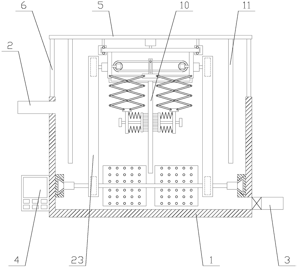
[0027] Such as figure 1 As shown, a sewage treatment device based on electrolytic air flotation includes an electrolytic cell 1, a water inlet pipe 2, a drain pipe 3, a controller 4, a top plate 5, a rotating mechanism, an agitating mechanism, an electrolytic mechanism and two pillars 6, and the The water inlet pipe 2 and the drain pipe 3 are respectively located on both sides of the electrolytic cell 1, the drain pipe 3 is provided with a valve, the controller 4 is fixed on the electrolytic cell 1, and the controller 4 is provided with a PLC. Both ends of the top plate 5 are respectively fixed above the electrolytic cell 1 by two pillars 6, the rotating mech...


PUM


Abstract

The invention relates to a sewage treatment device based on electrolytic flotation. The sewage treatment device based on electrolytic flotation comprises an electrolysis tank, a water inlet pipe, a drainage pipe, a roof, a rotating mechanism, a stirring mechanism, an electrolysis mechanism and two supporting columns, wherein the electrolysis mechanism comprises a sliding plate, a driving assembly,a negative plate, two cleaning assemblies and two positive plates, the cleaning assemblies comprise lifting plates, telescopic units, lifting plates, connecting frames and cleaning units, and the stirring mechanism comprises a rotating shaft, slides, two sliding blocks, two bearings, two rotating units and two stirring units. According to the sewage treatment device based on electrolytic flotation, through the stirring mechanism, sewage flows on the bottom of the interior of the electrolysis tank are stirred, convenience is brought for suspended particles on the bottom to be in contact with hydrogen bubbles to make electrolysis more fuller, moreover, when the electrolysis mechanism generates the hydrogen bubbles, through the telescopic units, the driving assembly drives the lifting platesto move vertically to make the cleaning units clean the surface of the negative plate and to enable the negative plate to be in full contact with sewage, the electrolysis efficiency is ensured, and the practicability of equipment is improved.

Description

technical field [0001] The invention relates to the field of water treatment equipment, in particular to a sewage treatment device based on electrolytic air flotation. Background technique [0002] Electrolytic air flotation refers to the introduction of direct current into the sewage, and a large number of tiny hydrogen bubbles with a diameter between 18 and 90 microns are generated on the surface of the cathode in the sewage. The hydrogen bubbles adhere to the small suspended particles in the wastewater, forming an overall density smaller than water. The "bubble particle" complex, the suspended particles float to the water surface together with the air bubbles, forming foam scum, so that the suspended solids in the water can be separated, a water treatment method, because the electrolytic air flotation has simple equipment, convenient management, and resource saving , good effect, etc., the electrolytic air flotation device is an ideal substitute for the traditional air fl...

Claims


Application Information

Patent Timeline
IPC IPC(8): C02F1/465C02F1/461
CPCC02F1/46104C02F1/465
Inventor 齐宽宽
Owner SHENZHEN JIUPIN AIR PURIFICATION TECH CO LTD
Why Eureka
Try Eureka