Eureka AIR delivers breakthrough ideas for toughest innovation challenges, trusted by R&D personnel around the world.

Adjustable precision increase device of radial drilling machine

A radial drilling machine, an adjustable technology, applied in the parts of boring machines/drilling machines, boring/drilling, metal processing equipment, etc., can solve the wear of the drill bit shell, the influence of the precision of the drill bit processing, and the unbalanced vibration frequency of the positioning frame. and other problems to achieve the effect of preventing damage

Inactive Publication Date: 2018-11-16
黄红兵
View PDF0 Cites 0 Cited by
  • Summary
  • Abstract
  • Description
  • Claims
  • Application Information

AI Technical Summary

Problems solved by technology

[0005] Aiming at the deficiencies in the prior art, the purpose of the present invention is to provide an adjustable precision increasing device for a radial drilling machine, so as to solve the problem that the positioning rack at the upper end of the drill bit vibrates during the high-speed rotation of the prior art drill bit, and the positioning machine The unbalanced vibration frequency of the frame will affect the precision of the drill bit processing. At the same time, during the drill bit processing process, the drill bit and the positioning frame are affected by the vibration force and come into contact. The drill shell is easy to wear under the long-term force.

Method used


Image

  • Adjustable precision increase device of radial drilling machine
  • Adjustable precision increase device of radial drilling machine
  • Adjustable precision increase device of radial drilling machine

Examples


Embodiment Construction

[0025] In order to make the technical means, creative features, goals and effects achieved by the present invention easy to understand, the present invention will be further described below in conjunction with specific embodiments.

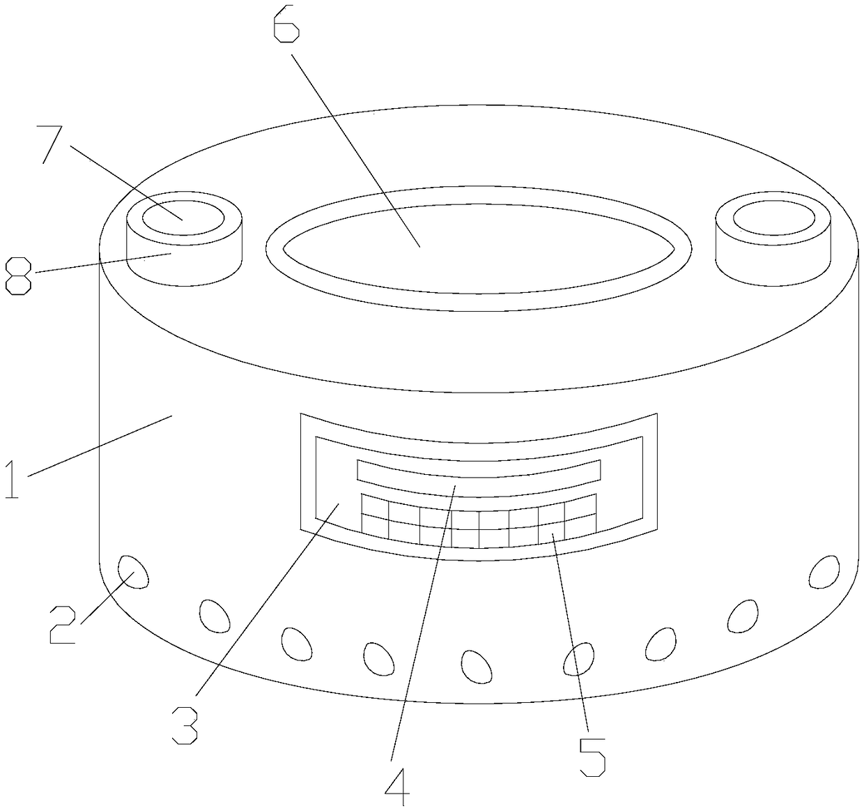
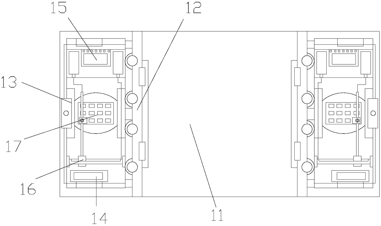
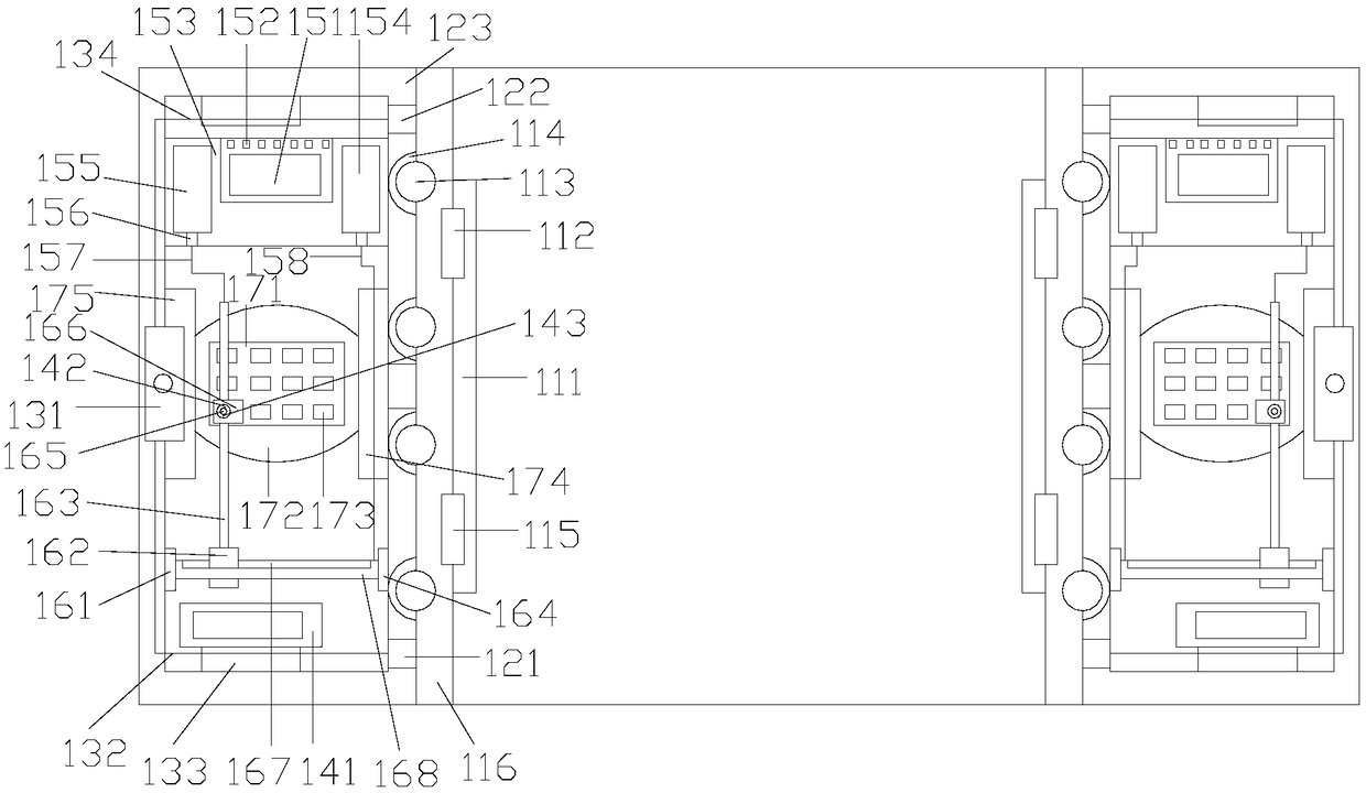
[0026] Such as Figure 1-Figure 5 As shown, the present invention provides a technical solution of an adjustable precision increasing device for a radial drilling machine:

[0027] An adjustable precision increasing device for a radial drilling machine, the structure of which includes an oscillating precision increasing device 1, a fixed balance weight 2, an adjustable panel 3, a data display screen 4, an adjustment button 5, a drill bit insertion port 6, a mounting positioning hole 7, Connecting the mounting block 8, the drill bit insertion port 6 is arranged in the center of the oscillating precision increasing device 1 and is an integrated structure, and the fixed balance weight 2 is arranged on the outer wall of the oscillating precision incre...


PUM


Abstract

The invention discloses an adjustable precision increase device of a radial drilling machine. The adjustable precision increase device structurally comprises a vibration type precision increase device, fixed balance blocks, an adjustable panel, a data display screen, adjusting buttons, a drill bit embedded opening, mounting locating holes and connecting mounting blocks. The drill bit embedded opening is arranged in the center of the vibration type precision increase device, and the drill bit embedded opening and the vibration type precision increase device are of an integrated structure. The fixed balance blocks are arranged on the outer wall of the vibration type precision increase device and are connected with the vibration type precision increase device in a welded manner. The adjustable panel is arranged on the outer wall of the vibration type precision increase device and is connected with the vibration type precision increase device in a fixed manner. The data display screen is electrically connected with the adjustable panel. The adjusting buttons are electrically connected with the adjustable panel. The adjustable precision increase device is provided with a structure for balancing the vibration frequency of the two sides of a drill bit in the drill bit rotating process, and the machining precision of the drill bit can be prevented from being influenced easily; and meanwhile, a structure of buffering and protecting a drill bit shell is arranged, and wear of a locating rack to the drill bit during use of the drill bit is effectively reduced.

Description

technical field [0001] The invention relates to the field of drilling machines, more precisely, an adjustable precision increasing device for a radial drilling machine. Background technique [0002] Drilling machines are mainly used for drilling workpieces. At present, drilling machines are widely used in mechanical processing plants. Drilling machines have the characteristics of high processing efficiency and simple operation. Drilling machines are often equipped with devices to adjust the accuracy of drill bits. However, the current precision increasing device has the following disadvantages: [0003] 1. During the high-speed rotation of the drill bit, the positioning rack at the upper end of the drill bit vibrates, and the unbalanced vibration frequency of the positioning rack will affect the precision of the drill bit processing. [0004] 2. At the same time, in the process of drill bit processing, the drill bit and the positioning frame are affected by the vibration fo...

Claims


Application Information

Patent Timeline
Patent Type & Authority Applications(China)
IPC IPC(8): B23B39/12B23B47/00B23Q11/00
CPCB23B39/12B23B47/00B23Q11/00
Inventor 黄红兵
Owner 黄红兵
Why Eureka
Eureka Blog
Learn More