
Compact type six-roller rolling mill and work method

A six-high rolling mill, compact technology, applied in the direction of metal rolling stand, metal rolling mill stand, metal rolling, etc., can solve the problem of difficult removal, oil adhesion, strong surface tension of oil film, bearing seat cannot be connected with spray Problems such as beam and oil retaining guide plate interference, etc., to achieve the effect of comprehensive functions, compact structure, and reducing residual oil

Pending Publication Date: 2018-11-16
CHINA NAT HEAVY MACHINERY RES INSTCO
View PDF0 Cites 2 Cited by
  • Summary
  • Abstract
  • Description
  • Claims
  • Application Information

AI Technical Summary

Problems solved by technology

These two parts should be arranged at the entrance and exit of the stand at the same time, and the upper intermediate roll and upper work roll of the conventional six-high rolling mill have their own roll changing tracks, and these devices cannot all be arranged in the narrow space of the small-diameter six-high rolling mill inside, and the bearing seat cannot interfere with the spray beam and the oil deflecting guide plate when changing the roll
Therefore, the conventional small-diameter six-high rolling mill usually sprays inside the rolling mill and removes oil outside the rolling mill. However, the adhesion of oil and the surface tension of the oil film are very strong, and once the oil drops on the strip, it is difficult to remove
[0005] Third, the intermediate rolls of traditional six-high mills need roll shifting, so that the effective overlapping width of the upper and lower intermediate rolls can be adjusted with the strip width to eliminate harmful contact areas. Therefore, the roll surface width of the intermediate rolls is basically the same as that of the work rolls and backup rolls. One problem brought about is that when the intermediate roll shifts, the roll neck of the intermediate roll and the roll surface of the work roll form a gap, causing the rolling oil to be sprayed directly from the strip inlet of the rolling mill to the strip exit of the rolling mill, resulting in the left a large amount of residual oil

Method used


Image

  • Compact type six-roller rolling mill and work method
  • Compact type six-roller rolling mill and work method
  • Compact type six-roller rolling mill and work method

Examples


Embodiment 1

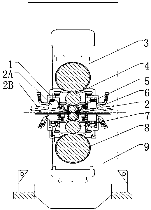
[0044] Such as figure 1 , 2 , 3, 4, 5, 6 and 7, a compact six-high rolling mill at least includes a frame 9, wherein the frame 9 includes at least a bottom fixing seat and two sets of support frames respectively fixed at the front and rear ends of the fixing seat , the two sets of supporting frames are all frame structures with the same structure, which is characterized in that: an upper support roll assembly 3, an upper intermediate roll assembly 4, an upper working roll assembly 5, a lower Work roll assembly 6, lower intermediate roll assembly 7 and lower backup roll assembly 8, in which the front and rear ends of upper backup roll assembly 3 and lower backup roll assembly 8 are respectively slidingly connected with two sets of support frames, upper work roll assembly 5 is connected with lower work roll assembly The roll assembly 6 has a symmetrical structure up and down. The upper intermediate roll assembly 4 and the lower intermediate roll assembly 7 have a vertically sym...

Embodiment 2

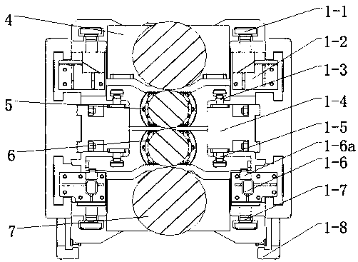
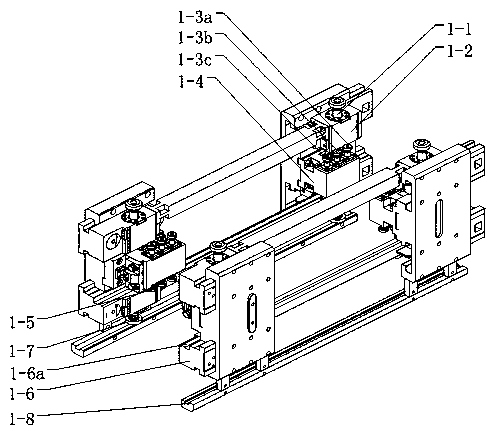
[0051] On the basis of Example 1, such as image 3 , 4 As shown in and 5, the roll bending device includes an upper intermediate roll bending cylinder block 1-2, a work roll bending cylinder block 1-4 and a lower intermediate roll bending cylinder block 1 which are sequentially fixed on the support from top to bottom -6, where the upper intermediate roll bending cylinder block 1-2 is provided with an upper intermediate roll bending cylinder piston 1-1, and the upper and lower working roll bending cylinder blocks 1-4 are respectively provided with an upper working roll bending cylinder piston 1-3 and the lower working roll bending cylinder piston 1-5, the lower middle roll bending cylinder piston 1-7 is arranged under the lower middle roll bending cylinder block 1-6; among them, the upper working roll bending cylinder piston 1-3 It consists of the first piston 1-3a, the second piston 1-3b and the third piston 1-3c arranged in a straight line from front to back. The structure o...

Embodiment 3

[0056] On the basis of embodiment 1 or 2, such as Figure 5 As shown, the upper intermediate roller piston mechanism includes an upper intermediate roller nitrogen piston 4-1 and an upper intermediate roller guide post 4-3, and the upper intermediate roller guide post 4-3 is set outside the upper intermediate roller nitrogen piston 4-1 and inside It is connected with the upper intermediate roller nitrogen piston 4-1, and the upper intermediate roller guide column 4-3 is also provided with a step;

[0057] The upper work roll piston mechanism includes an upper work roll nitrogen piston 5-2 and an upper work roll guide post 5-3, the upper work roll guide post 5-3 is set outside the upper work roll nitrogen piston 5-2 and the inner part is connected with the upper work roll Roll nitrogen piston 5-2 connection;

[0058] The lower intermediate roller piston mechanism includes a lower intermediate roller nitrogen piston 7-1 and a lower intermediate roller guide post 7-3. The nitro...


PUM


Abstract

The invention relates to a compact type six-roller rolling mill and a work method. The compact type six-roller rolling mill comprises a work roller and intermediate roller bending cylinder block, spraying beam and oil stopping guide plate parts, an upper bearing roller assembly, an upper intermediate roller assembly, an upper work roller assembly, a lower work roller assembly, a lower intermediateroller assembly, a lower bearing roller assembly and a rack. According to the compact type six-roller rolling mill and the work method, plate shape condition means such as intermediate roller positive and negative roller bending, work roller smooth transition positive and negative roller bending and intermediate roller channeling are achieved; the inner structure of the rack is compact, the spraying beam and oil stopping guide plate parts are arranged in the small space strip inlet and outlet direction, the outlet strip surface residual oil is reduced, and residual oil sprayed to the outlet strip surface from the empty space between the intermediate roller diameter part and a work roller during intermediate roller channeling can be greatly reduced.

Description

technical field [0001] The invention relates to a six-high rolling mill in the field of cold rolling, in particular to a compact six-high rolling mill and a working method. Background technique [0002] In the production process of special steel strips, due to the variety of product materials, such as high-nickel, low-nickel alloys, soft magnetic alloys, spring steel, etc., there are both high-hardness materials and soft materials; due to the range of product thickness variation wide, the thickest incoming material is 5mm, and the thinnest product can be produced at 0.2mm. The production process arrangement is flexible, and the requirements for product precision and intrinsic performance of materials are relatively high. Due to the need to produce thin gauge hard stock, small diameter work rolls must be used. The difficulty of this type of rolling mill is that the small-diameter work rolls bring about small bearing housings and small rack space, and at the same time, funct...

Claims


Application Information

Patent Timeline
IPC IPC(8): B21B13/06B21B31/08
CPCB21B13/06B21B31/08
Inventor 尤磊苏旭涛窦锋赵晓辉计江
Owner CHINA NAT HEAVY MACHINERY RES INSTCO
Learn More