
A radiation-resistant and bending-resistant reinforced optical cable

A strengthened, radiation-resistant technology, applied in the field of optical cables, can solve problems such as internal structure breakage and insufficient bending strength, and achieve the effect of protecting optical fibers

Active Publication Date: 2020-06-12
HANGZHOU FUTONG COMM TECH CO LTD
View PDF5 Cites 0 Cited by
  • Summary
  • Abstract
  • Description
  • Claims
  • Application Information

AI Technical Summary

Problems solved by technology

[0004] The purpose of the present invention is to solve the shortcomings in the prior art, such as: optical cables often need to be bent during use, the bending resistance is not strong enough, and the internal structure is likely to be damaged, and a radiation-resistant and bending-resistant reinforced optical cable is proposed.

Method used


Image

  • A radiation-resistant and bending-resistant reinforced optical cable
  • A radiation-resistant and bending-resistant reinforced optical cable
  • A radiation-resistant and bending-resistant reinforced optical cable

Examples


Embodiment Construction

[0018] The following will clearly and completely describe the technical solutions in the embodiments of the present invention with reference to the accompanying drawings in the embodiments of the present invention. Obviously, the described embodiments are only some, not all, embodiments of the present invention.

[0019] In describing the present invention, it should be understood that the terms "upper", "lower", "front", "rear", "left", "right", "top", "bottom", "inner", " The orientation or positional relationship indicated by "outside", etc. is based on the orientation or positional relationship shown in the drawings, and is only for the convenience of describing the present invention and simplifying the description, rather than indicating or implying that the referred device or element must have a specific orientation, so as to Specific orientation configurations and operations, therefore, are not to be construed as limitations on the invention.

[0020] refer to Figure ...


PUM


Abstract

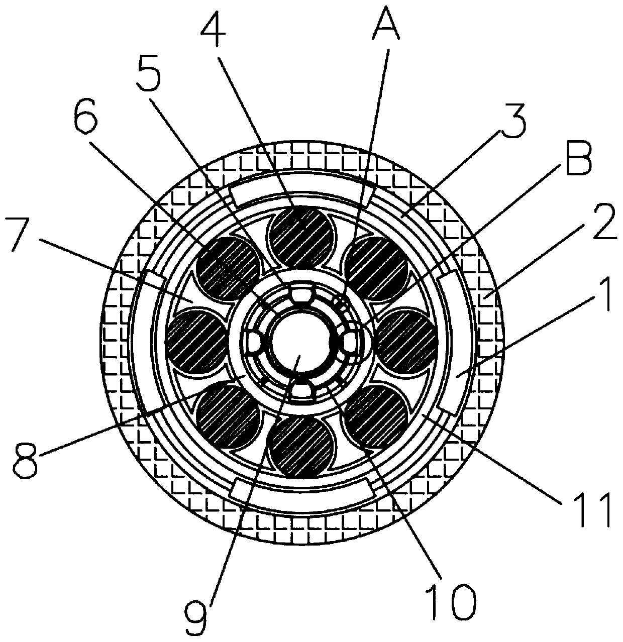
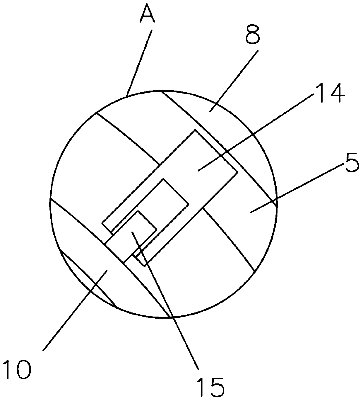
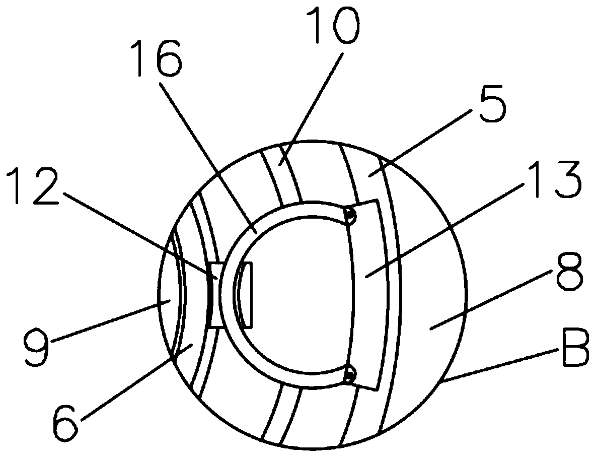
The invention discloses a radiation-resistant and bending-resistant reinforced optical cable, which includes a first outer sleeve and a plurality of first optical fibers. The plurality of first optical fibers are installed in the first outer sleeve. A first inner sleeve is arranged between, and the first inner sleeve is sleeved on a plurality of first optical fibers, and an active layer is arranged between the first outer sleeve and the first inner sleeve, and the inner sleeve of the active layer A movable ring is installed, and the movable ring includes a plurality of arc shafts and a plurality of arc sleeves, the two ends of the arc shafts are respectively inserted in two arc sleeves, and the arc shafts and The positions of the first optical fibers are installed alternately, and the inner sides of the plurality of first optical fibers are installed with second inner sleeves. The invention separates the optical fibers from each other to avoid damage caused by mutual friction, extrusion and friction, and at the same time protects the optical fibers. At the same time, the movable mechanism and the elastic mechanism ensure that the optical cable has a certain movable space and can prevent damage to the internal structure. .

Description

technical field [0001] The invention relates to the technical field of optical cables, in particular to a radiation-resistant and bending-resistant reinforced optical cable. Background technique [0002] A fiber optic cable is a communication cable consisting of two or more glass or plastic optical fiber cores within a protective cladding covered by a plastic PVC outer sleeve. The signal transmission along the internal optical fiber generally uses infrared rays. Optical fiber communication is one of the important ways of modern information transmission. It has the advantages of large capacity, long relay distance, good confidentiality, no electromagnetic interference and copper saving. [0003] However, optical cables often need to be installed over a long distance, and the length of the installation is very long. Because the wiring is very complicated, there are many angles and positions that need to be bent. If the optical cable is too bent, it is easy to break the optical...

Claims


Application Information

Patent Timeline
Patent Type & Authority Patents(China)
IPC IPC(8): G02B6/44
CPCG02B6/443
Inventor 郭鹏
Owner HANGZHOU FUTONG COMM TECH CO LTD
Learn More