
Internal one-way valve

A one-way valve, built-in technology, applied in the direction of valve details, control valves, valve devices, etc., can solve the problems of limited size and installation position, increased cost, weight, high tolerance accuracy, etc., to reduce fluid resistance and save equipment space , the effect of improving the structural strength

Pending Publication Date: 2018-11-13
上海银轮热交换系统有限公司
View PDF0 Cites 1 Cited by
  • Summary
  • Abstract
  • Description
  • Claims
  • Application Information

AI Technical Summary

Problems solved by technology

The one-way valve on small equipment is generally composed of valve body, piston valve body, and fixed valve seat, and has many parts. Considering factors such as leakage, vibration, noise, pressure resistance, and temperature change, the production process The requirements are relatively high, the tolerance precision of each part is high, and it takes up a lot of space at the same time
For a small module containing a one-way valve and limited space size, it not only increases the cost and weight, but also limits the size and installation location of other components, especially in small equipment with limited space, such as automotive air conditioners, aircraft, satellites Equal cooling system, the impact of the check valve volume on the equipment is more serious
[0004] In addition, the existing one-way valve suitable for small equipment modules also has the defect of high manufacturing cost

Method used


Image

  • Internal one-way valve
  • Internal one-way valve
  • Internal one-way valve

Examples


Embodiment Construction

[0076] The technical solution of the present invention will be further described in detail with specific embodiments below in conjunction with the accompanying drawings. It should be understood that the following examples are only used to illustrate the present invention but not to limit the scope of the present invention.

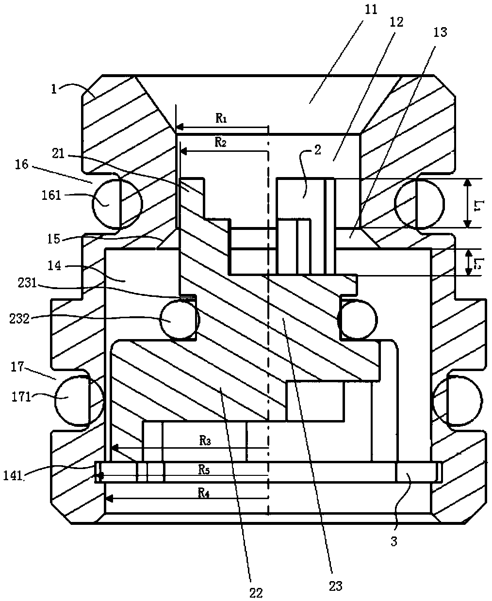
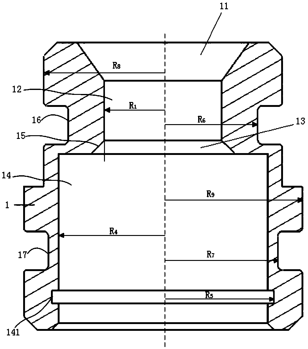
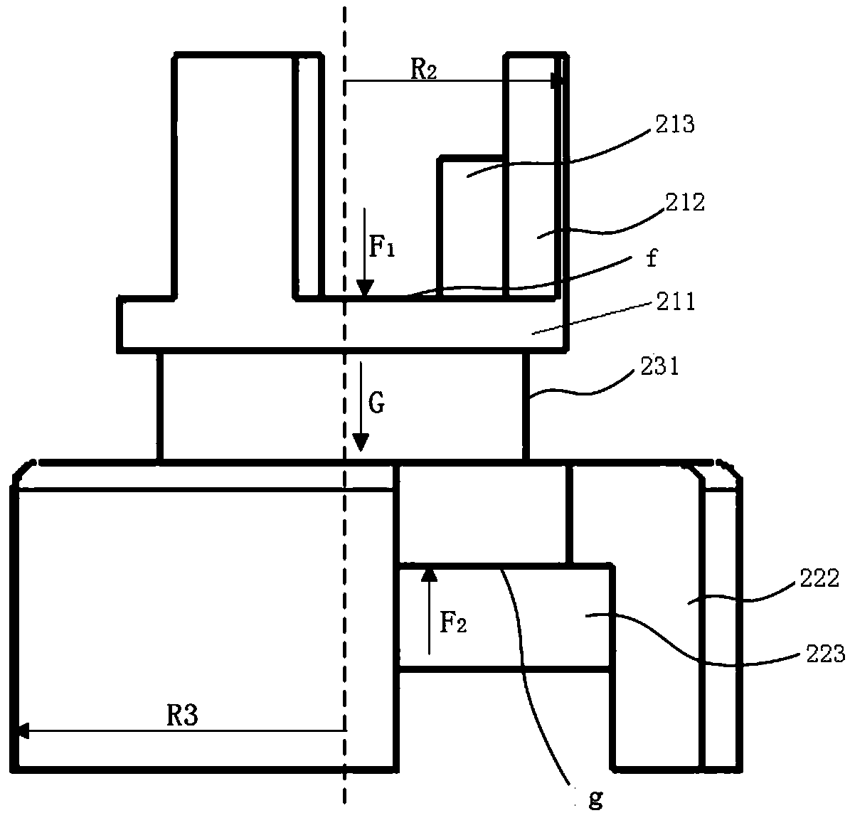
[0077] like Figure 1 to Figure 4 As shown, according to the first embodiment of the present invention, the built-in check valve of the present invention includes a valve body 1 , a valve core 2 and a snap ring 3 . in:

[0078] like figure 1 and figure 2 As shown, the inside of the valve body 1 has a circular cavity, and the circular cavity includes an inlet flow channel 11, a neck flow channel 12, a throat flow channel 13 and The outlet channel 14, the inlet channel 11, the neck channel 12, the throat channel 13 and the outlet channel 14 are concentric. The fluid enters the outlet channel 14 through the inlet channel 11 , the neck channel 12 and the...


PUM


Abstract

The invention provides an internal one-way valve. The internal one-way valve comprises a valve body, a valve element and a clamp spring. An inlet channel, a neck channel, a throat channel and an outlet channel which are sequentially connected are arranged in the valve body. The inner wall, corresponding to the throat channel, of the valve body is an oblique conical face. The inlet channel, the neck channel, the throat channel and the outlet channel are concentric. The valve element comprises a valve element head, a valve element tail and a middle connection section. An annular internal seal groove is formed in the middle connection section. An annular clamp spring clamping groove is formed in the inner wall of the tail end of the outlet channel. The clamp spring is arranged in the clamp spring clamping groove. An inlet fluid pressure-bearing face is arranged on the valve element head, and an outlet fluid pressure-bearing face is arranged on the valve element tail. The internal one-wayvalve can be independently mounted and can also be mounted in a connecting piece body, so that the equipment space is saved, and the equipment weight is reduced; and the internal one-way valve can reciprocate and slightly deflect in the flowing direction of fluid in the channels and can also rotate, so that the resistance of the fluid is greatly reduced; and the noise is low, and the structural strength is high.

Description

technical field [0001] The invention belongs to the field of mechanical equipment, in particular, a built-in check valve is designed. Background technique [0002] With the rapid development of science and technology, all walks of life have higher and higher requirements for the miniaturization and compactness of mechanical equipment. There are often multiple bifurcated flow channels inside a mechanical equipment, or even multiple fluid media. It is hoped that the medium will flow in the desired flow direction under different conditions. Due to the disorder of fluid movement, it is necessary to add a one-way valve in the flow channel to limit the flow direction of the fluid and prevent the occurrence of fluid cross-flow and reverse flow. Especially in the small equipment that needs to prevent the reverse flow of the medium, but the pressure does not exceed 20MPa, and the fluid medium is not strongly corrosive, it is necessary to add a check valve, such as in the pipeline of...

Claims


Application Information

Patent Timeline
IPC IPC(8): F16K15/02F16K47/04
CPCF16K15/02F16K47/045
Inventor 王超杨云郭培培顾毅亮吴俊
Owner 上海银轮热交换系统有限公司
Learn More