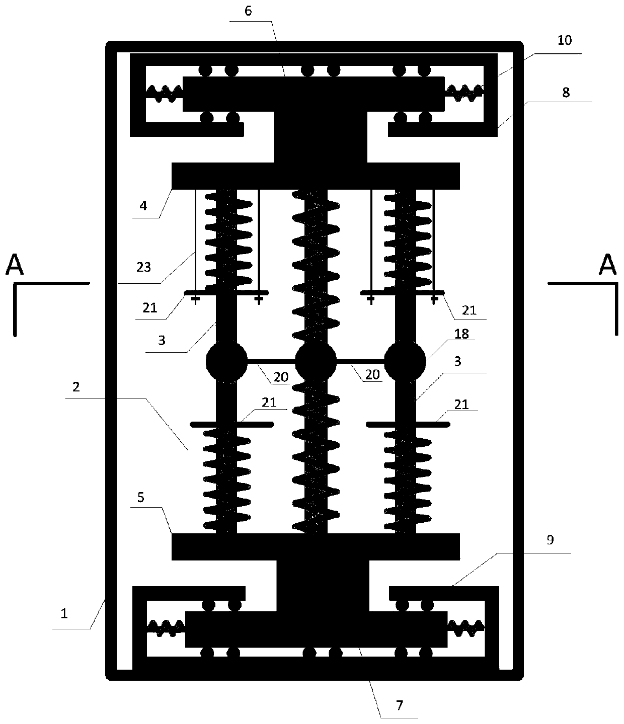
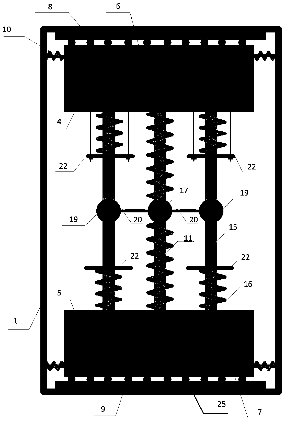
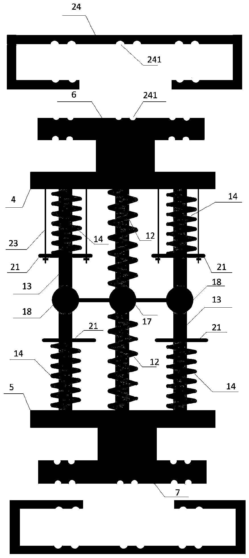
A vibration damping device and parameter adjustment method thereof

A technology of vibration damping device and damping mechanism, applied in the direction of shock absorber, shock absorber, spring/shock absorber, etc., can solve the application of limiting structural vibration control, the vibration damping device has a single natural vibration frequency, and the vibration damping effect Poor and other problems, to achieve the effect of reducing health monitoring control, good vibration reduction effect, and expanding application adaptability

Active Publication Date: 2020-01-03
ANHUI TRANSPORTATION HLDG GRP CO LTD
View PDF6 Cites 0 Cited by
  • Summary
  • Abstract
  • Description
  • Claims
  • Application Information

AI Technical Summary

Problems solved by technology

[0006] The embodiment of the present invention provides a vibration damping device, which aims to solve the problems of directional control and single natural vibration frequency in the existing vibration damping device, which can only provide limited damping for the structure, which limits its application in structural vibration control, and is difficult Maintain a good vibration damping effect at each stage, the problem of poor vibration damping effect

Method used


Image

  • A vibration damping device and parameter adjustment method thereof
  • A vibration damping device and parameter adjustment method thereof
  • A vibration damping device and parameter adjustment method thereof

Examples


Embodiment Construction

[0041] In order to make the object, technical solution and advantages of the present invention clearer, the present invention will be further described in detail below in conjunction with the accompanying drawings and embodiments. It should be understood that the specific embodiments described here are only used to explain the present invention, not to limit the present invention.

[0042] Embodiments of the present patent are described in detail below, examples of which are shown in the drawings, wherein the same or similar reference numerals designate the same or similar elements or elements having the same or similar functions throughout. The embodiments described below by referring to the figures are exemplary and are only used for explaining the patent, and should not be construed as limiting the patent.

[0043] In the description of this patent, it is to be understood that the terms "center", "upper", "lower", "front", "rear", "left", "right", "vertical", "horizontal", ...


PUM


Abstract

The invention is applicable to the field of structural health monitoring, and provides a vibration reduction device and a parameter adjustment method thereof. The vibration reduction device comprisesa box body and a vibration reduction mechanism arranged in the box body; the vibration reduction mechanism comprises a plurality of vertically arranged sleeve rods, and a first steel plate and a second steel plate, wherein elastic components are arranged on the sleeve rods correspondingly, the plurality of sleeve rods form a plurality of groups of adjustable frequency ratios so as to realize multi-stage control of a structure in the vertical direction, and the first steel plate and the second steel plate correspondingly connected to the upper end and the lower end of each sleeve rod; the middle part of the first steel plate and the middle part of the second steel plate are correspondingly connected to the upper part of a first sliding base and the upper part of a second sliding base, and the lower part of the first sliding base and the lower part of the second sliding base are correspondingly movably nested into a first steel ball track assembly and a second steel ball track assembly correspondingly; and elastic devices are correspondingly arranged in the horizontal directions between the four side surfaces, namely the front side surfaces, the rear side surfaces, the left side surfaces and the right side surfaces, of the lower parts of the first sliding base and the second sliding base and the inner side surfaces of the first steel ball track assembly and the second steel balltrack assembly. The vibration reduction device can realize the multi-stage bidirectional control of vibration in the vertical and horizontal directions of the structure, the vibration reduction effectis effectively improved, and the application range is wide.

Description

technical field [0001] The invention belongs to the field of structural health monitoring, in particular to a vibration damping device and a parameter adjustment method thereof. Background technique [0002] In steel-concrete continuous composite girder bridges, due to the high tensile strength of steel and good compressive performance of concrete, the composite beams in the positive bending moment zone just give full play to the superior material properties of steel and concrete, so it is accepted and favored by the majority of bridge engineers. recognized. When a vehicle runs on a bridge, it will have a dynamic impact on the bridge structure, causing the bridge to vibrate, and the vibration of the bridge structure will in turn affect the vehicles running on the bridge. In this way, vehicle vibration and bridge structure vibration interact to form a complex multi-degree-of-freedom vibration system. Therefore, it is of great significance to study the bridge structure vibra...

Claims


Application Information

Patent Timeline
Patent Type & Authority Patents(China)
IPC IPC(8): F16F7/116E01D19/00
CPCE01D19/00F16F7/116
Inventor 胡可王佐才丁雅杰任伟新马祖桥何金武袁助赵金磊许垒
Owner ANHUI TRANSPORTATION HLDG GRP CO LTD
Why Eureka
Try Eureka