Moving bed biofilm sewage treatment device

A sewage treatment device, moving bed biofilm technology, applied in biological water/sewage treatment, sustainable biological treatment, water/sewage multi-stage treatment, etc. Unbalanced moving state and other problems, to achieve the effect of sufficient repeated contact and scouring, reducing energy consumption of aeration and fluidization, and improving hydraulic flow characteristics

Inactive Publication Date: 2018-11-13
HUBEI DINGYU ENVIRONMENTAL PROTECTION TECH
View PDF7 Cites 1 Cited by
  • Summary
  • Abstract
  • Description
  • Claims
  • Application Information

AI Technical Summary

Problems solved by technology

[0006] But at present, it is difficult to do it in most of the actual engineering design. Therefore, in the actual engineering, it exists to varying degrees. Balanced, prone to the defects of local filler accumulation; or blindly increase the aeration volume in order to overcome these defects, resulting in excessive aeration energy consumption
[0007] 2. Due to the special hydraulic characteristic requirements of MBBR reactor, it is difficult to realize large-scale
[0008] 3. The possible disadvantages of the large-scale MBBR reactor
However, the backflow of fillers will greatly increase the energy consumption of the system. At the same time, the fillers collide with each other in the pipeline, which will cause a large amount of anaerobic and anoxic biofilms to fall off on the fillers and affect the treatment effect of the system; Filling blockage is prone to occur. In addition, the underwater agitators arranged in random places are prone to hydraulic dead angles, which also lead to a large amount of fillers accumulating in the dead water area.
Otherwise, it is necessary to set up a high-power agitator to stir, and the stirring intensity is too high, firstly, it will cause excessive energy consumption, and secondly, it will cause the wear of the suspended filler and the difficulty of attaching the biofilm on the filler
[0009] 4. The outlet of the MBBR reactor is equipped with grids and grids to intercept suspended fillers, which are prone to blockage
[0010] 5. The suspended matter in the effluent water of MBBR reactor is so small that it is difficult to settle, separate and purify
The suspended filler in the MBBR reactor is scoured and collided with the gas-liquid flow, and the aging biofilm can be shed and renewed in time, which improves the efficiency of biochemical treatment of sewage; but at the same time, there are tiny bubbles attached to the reactor effluent. Suspended matter of biofilm debris is difficult to effectively settle and separate, affecting the quality of effluent water, etc.

Method used


Image

  • Moving bed biofilm sewage treatment device
  • Moving bed biofilm sewage treatment device
  • Moving bed biofilm sewage treatment device

Examples


Embodiment 1

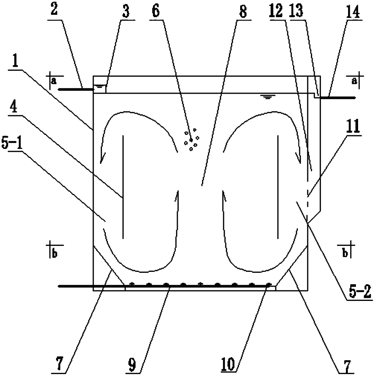
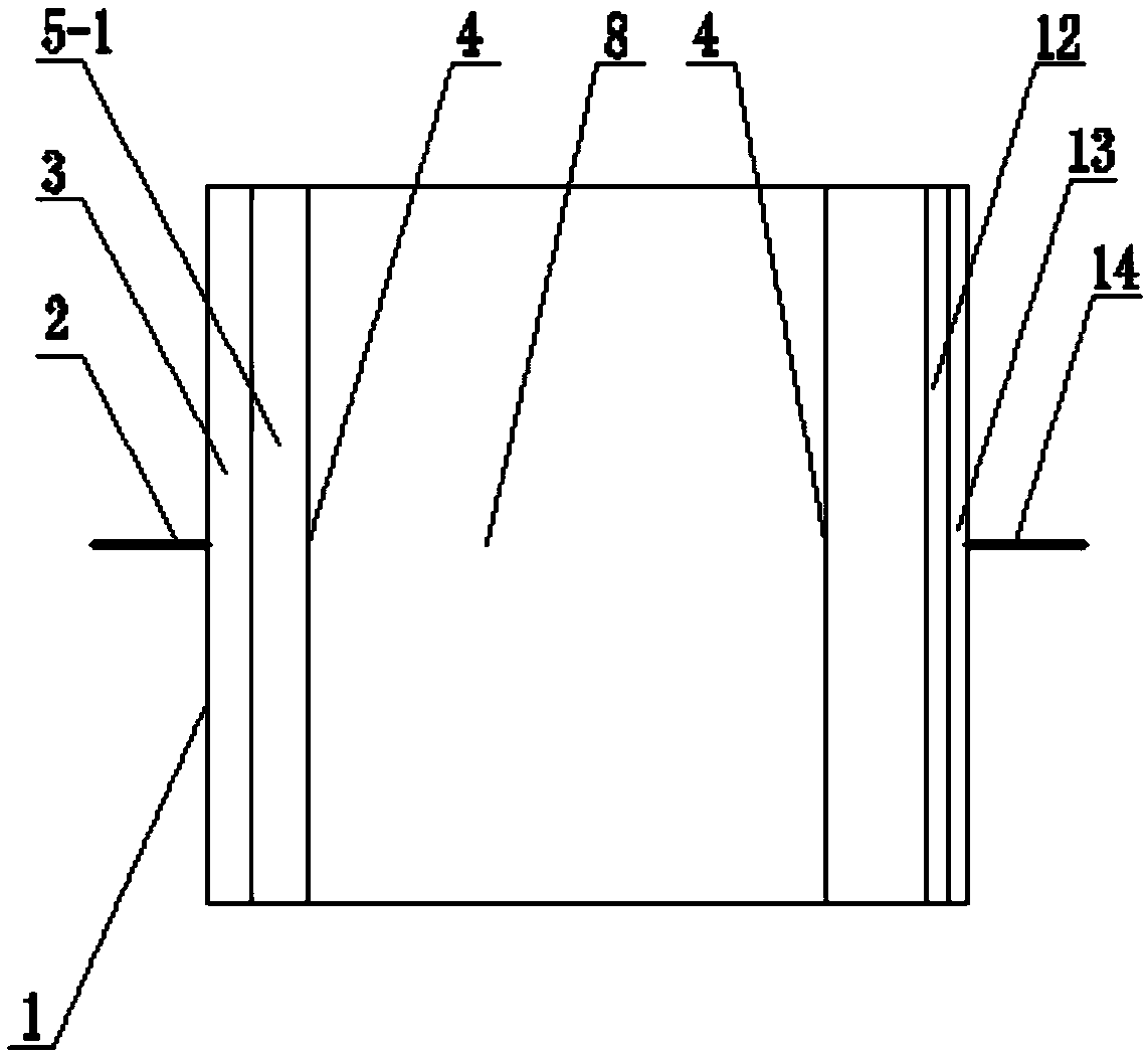
[0051] Such as Figures 1-1 to 1-5 As shown, in this embodiment, a water outlet groove 12 is provided on the outer wall of the peripheral partition wall of the pool body 1 on the other side corresponding to the water inlet hole, and the water outlet hole and the water outlet pipe 14 connected to the water outlet hole are arranged in the water outlet groove. The upper position of 12; the peripheral partition wall on the side where the outlet tank 12 is located is provided with a flow hole for installing the outlet screen 11; Water collection channel 13; the outlet screen 11 has strip or circular holes.

[0052] In this embodiment, the sewage to be treated is transported to the water inlet pipe 2 through the water inlet pump, enters the water distribution overflow weir groove 3 through the water inlet pipe 2, overflows evenly from the top of the water distribution weir into the water surface of the pool body 1, and is immediately aerated with the middle aeration zone 8 The wate...

Embodiment 2

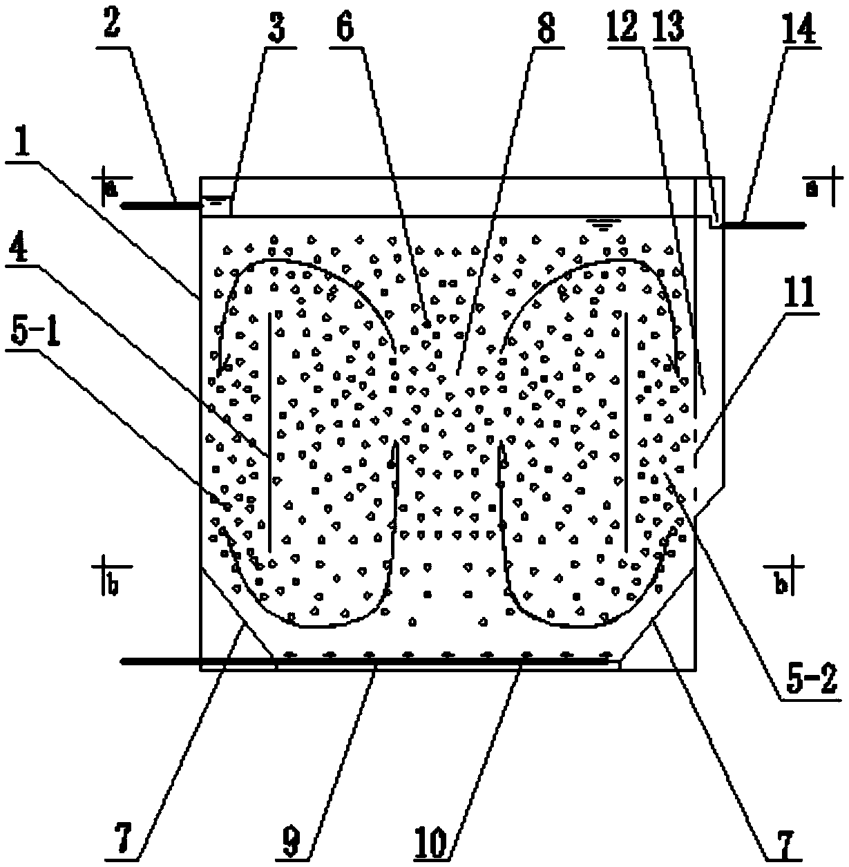
[0057] Such as Figures 2-1 to 2-6 As shown, the inner wall above the outer partition wall on the water outlet side of the pool body 1 is obliquely provided with a water outlet screen 11, and the water collection channel 13 is located between the water outlet screen 11 and the outer partition wall, and the water flow can flow through the outlet screen. 11 The overflow flows into the water collection channel 13; the outlet screen 11 is a bow-shaped bent plate grille, the two straight side plates of the bow-shaped bent plate are solid plates, and the middle hypotenuse plate has strip-shaped or circular holes.

[0058] In this embodiment, the sewage to be treated is transported to the water inlet pipe 2 through the water inlet pump, enters the water distribution overflow weir groove 3 through the water inlet pipe 2, overflows evenly from the top of the water distribution weir into the water surface of the pool body 1, and is immediately aerated with the middle aeration zone 8 The...


PUM


Abstract

The invention provides a moving bed biofilm sewage treatment device, comprising a pool body which is used for biochemical treatment of sewage and is defined by external partitions; the upper part of the external partition at any side of the pool body is provided with a water inlet hole and a water inlet pipe connected with the water inlet hole; an overflow weir groove for water distribution is formed at one side of the water inlet hole, and the water inlet hole is communicated with the overflow weir groove for water distribution; the upper part of the external partition at the other side, corresponding to the water inlet hole, of the pool body is provided with a water outlet hole and a water outlet pipe connected with the water outlet hole; a water collecting channel is arranged at one side of the water outlet hole, and the water outlet hole is communicated with the water collecting channel; two vertical guide plates are symmetrically arranged at the positions, corresponding to the water inlet side and the water outlet side, in the pool body; the interior of the pool body is sequentially divided into a return channel area at the water inlet side, a middle aeration area and a returnchannel area at the water outlet side by means of the guide plates; the pool body is internally filled with suspended filler. The moving bed biofilm sewage treatment device is compact in structure, and enables aerobic and anoxic biochemical processes of sewage treatment to be completed in an integrated unit so as to guarantee the sewage purification treatment efficiency.

Description

technical field [0001] The invention relates to the field of sewage treatment, in particular to a moving bed biofilm sewage treatment device. Background technique [0002] The moving bed biofilm reactor (MBBR) process absorbs the advantages of the traditional fluidized bed and biological contact oxidation processes. The core is to directly add a certain proportion of suspended fillers with a specific gravity close to water into the reactor, as microorganisms. The active carrier can greatly increase the biomass and biological species in the reactor, thus greatly improving the efficiency of sewage treatment. [0003] As a process that combines the activated sludge method of suspended growth and the biofilm method of attached growth, the current MBBR reactor has the advantages of both, and has the outstanding advantages of simple operation, small footprint, and high treatment efficiency; but In the biochemical treatment tank, there are also aeration dead zones to varying degre...

Claims


Application Information

Patent Timeline
Patent Type & Authority Applications(China)
IPC IPC(8): C02F3/12C02F9/14
CPCC02F1/001C02F3/1268Y02W10/10
Inventor 王雷徐刚梁正平
Owner HUBEI DINGYU ENVIRONMENTAL PROTECTION TECH
Why Eureka
Try Eureka