Jewel-crafting worktable

A workbench and jewelry technology, applied in the direction of workbench, manufacturing tools, etc., can solve the problems that jewelry processing workbench cannot meet people’s needs, easy to accumulate large debris, and inconvenient to pick and place tools, so as to achieve convenient classification and placement, Reasonable use of space, convenient and quick effect

Active Publication Date: 2018-11-13
深圳市朗耀电子商务有限公司
View PDF8 Cites 2 Cited by
  • Summary
  • Abstract
  • Description
  • Claims
  • Application Information

AI Technical Summary

Problems solved by technology

[0002] Jewelry processing workbench is a kind of workbench used for grinding and polishing jewelry. However, with the development of technology, people have higher and higher requirements for jewelry processing workbench. As a result, traditional jewelry processing workbench can no longer be used Meet people's needs;
[0003] There are certain drawbacks in the use of existing jewelry processing workbenches. (1) During jewelry processing, multiple tools need to be used at the same time, and the existing jewelry processing workbench can only be increased by increasing the horizontal or vertical desktop size of the workbench. , to improve, but, because the desktop is larger, it is inconvenient for the user to take and place the tools at the far position of the desktop; (2), the existing workbench placement box can only move back and forth like a drawer, and the user is using When working at the workbench, it is necessary to move back and forth to open the placement box, and then to work again after closing, which brings certain inconvenience to the user; (3), when the existing jewelry processing workbench is used, a large amount of jewelry is easy to accumulate on the surface of the workbench. When cleaning, the surface of the workbench can only be cleaned manually, which is relatively cumbersome, and at the same time it is difficult to clean some corners. Therefore, we propose a jewelry processing workbench

Method used


Image

  • Jewel-crafting worktable
  • Jewel-crafting worktable
  • Jewel-crafting worktable

Examples


Embodiment 1

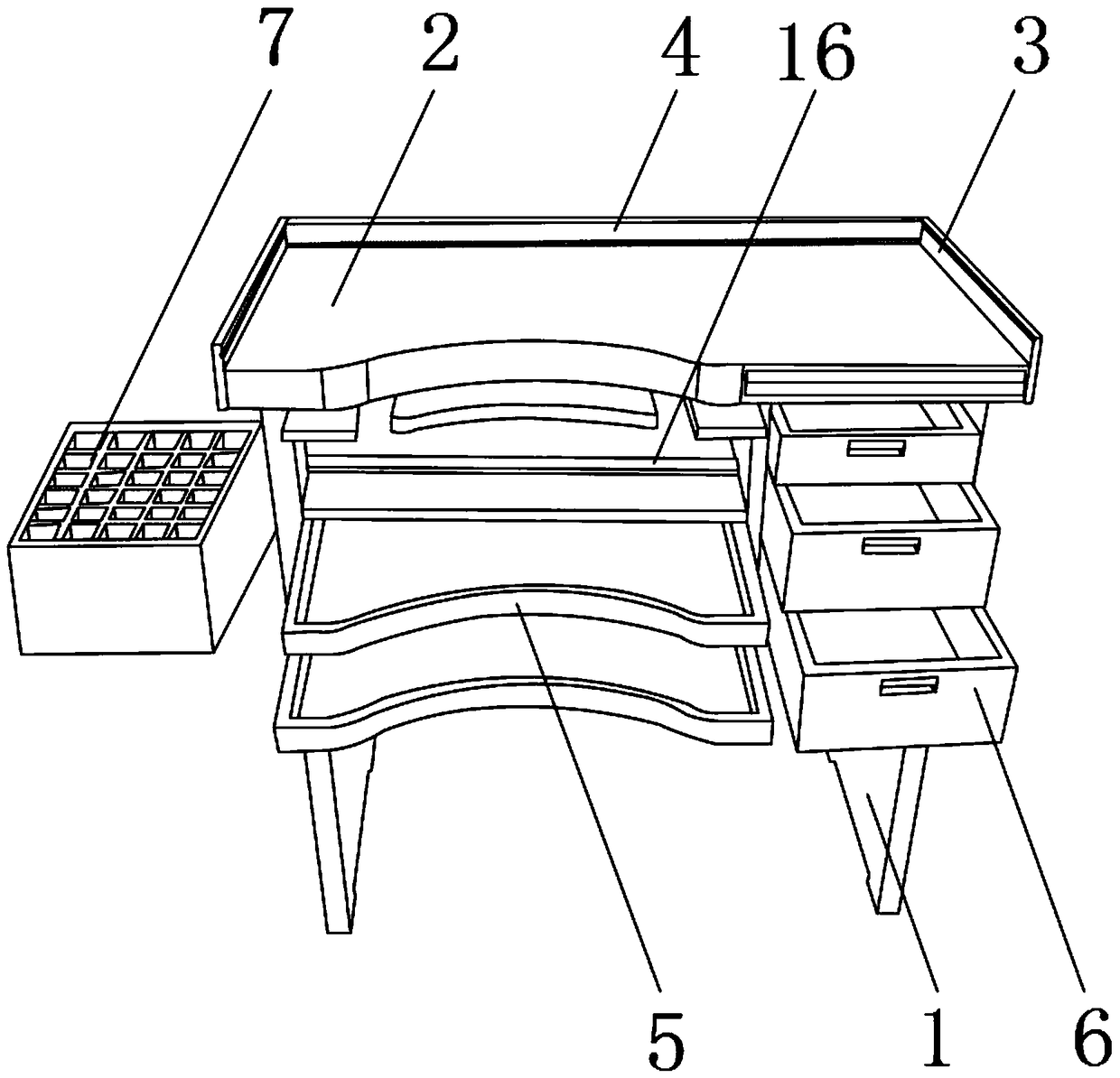
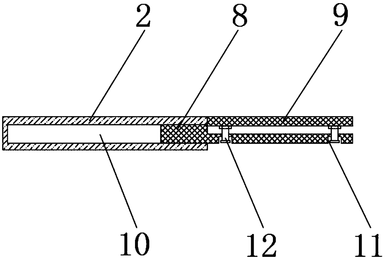
[0026] Such as Figure 1-5 As shown, including the support frame 1, the top outer surface of the support frame 1 is fixed with the workbench 2 by bolts, and the top outer surface of the workbench 2 is fixed with protective side plates 3 by bolts near the two sides, and the two sets of protective side plates A movable plate 4 is movably installed between the 3, and the inside of the support frame 1 near the front end is movably installed with a placement plate 5 and a drawer 6 through slide rails, and the drawer 6 is located on one side of the placement plate 5, and one side of the support frame 1 is outside. The surface is provided with a placement box 7 near the top position, and the inside of the workbench 2 is provided with a guide groove 10 near the front end, and the inner bottom surface of the guide groove 10 is movably installed with a support base plate 8 through slide rails, and the top outer surface of the support base plate 8 is movably installed. There is a connect...

Embodiment 2

[0030] Such as Figure 1-5 As shown, including the support frame 1, the top outer surface of the support frame 1 is fixed with the workbench 2 by bolts, and the top outer surface of the workbench 2 is fixed with protective side plates 3 by bolts near the two sides, and the two sets of protective side plates A movable plate 4 is movably installed between the 3, and the inside of the support frame 1 near the front end is movably installed with a placement plate 5 and a drawer 6 through slide rails, and the drawer 6 is located on one side of the placement plate 5, and one side of the support frame 1 is outside. The surface is provided with a placement box 7 near the top position, and the inside of the workbench 2 is provided with a guide groove 10 near the front end, and the inner bottom surface of the guide groove 10 is movably installed with a support base plate 8 through slide rails, and the top outer surface of the support base plate 8 is movably installed. There is a connect...

Embodiment 3

[0034] Such as Figure 1-5 As shown, including the support frame 1, the top outer surface of the support frame 1 is fixed with the workbench 2 by bolts, and the top outer surface of the workbench 2 is fixed with protective side plates 3 by bolts near the two sides, and the two sets of protective side plates A movable plate 4 is movably installed between the 3, and the inside of the support frame 1 near the front end is movably installed with a placement plate 5 and a drawer 6 through slide rails, and the drawer 6 is located on one side of the placement plate 5, and one side of the support frame 1 is outside. The surface is provided with a placement box 7 near the top position, and the inside of the workbench 2 is provided with a guide groove 10 near the front end, and the inner bottom surface of the guide groove 10 is movably installed with a support base plate 8 through slide rails, and the top outer surface of the support base plate 8 is movably installed. There is a connect...


PUM


Abstract

The invention discloses a jewel-crafting worktable. The jewel-crafting worktable comprises a supporting frame; a worktable is fixed to the outer surface of the top end of the supporting frame througha bolt; the positions, close to the two sides, of the outer surface of the top end of the worktable are each fixedly provided with a protective side plate through a bolt; the positions, close to the front end, of the inside of the supporting frame are each movably provided with a placing plate and a drawer by virtue of sliding rails; and each drawer is positioned at one side of the corresponding placing plate. According to the jewel-crafting worktable disclosed by the invention, firstly the usable area of the worktable can be increased; meanwhile a connecting plate is arranged around a user sothat a tool can be taken and placed more conveniently and quickly, and the work efficiency is improved; secondly, the tool can be taken and placed more conveniently; meanwhile, the user needs not tomove to take and place the tool; the jewel-crafting worktable can preferably meet different needs of the user; moreover, the surface of the worktable can be cleaned when a movable plate moves so thatthe worktable can be cleaned more conveniently and simply; and better application prospects can be provided.

Description

technical field [0001] The invention relates to the field of workbenches, in particular to a jewelry processing workbench. Background technique [0002] Jewelry processing workbench is a kind of workbench used for grinding and polishing jewelry. However, with the development of technology, people have higher and higher requirements for jewelry processing workbench. As a result, traditional jewelry processing workbench can no longer be used Meet people's needs; [0003] There are certain drawbacks in the use of existing jewelry processing workbenches. (1) During jewelry processing, multiple tools need to be used at the same time, and the existing jewelry processing workbench can only be increased by increasing the horizontal or vertical desktop size of the workbench. , to improve, but, because the desktop is larger, it is inconvenient for the user to take and place the tools at the far position of the desktop; (2), the existing workbench placement box can only move back and ...

Claims


Application Information

Patent Timeline
Patent Type & Authority Applications(China)
IPC IPC(8): B25H1/02B25H1/12B25H1/14
CPCB25H1/02B25H1/12B25H1/14
Inventor 洪树钺
Owner 深圳市朗耀电子商务有限公司
Why Eureka
Try Eureka