Fiber pretreatment device and use method thereof
A pretreatment device and fiber technology, applied in spray/jet textile material processing and other directions, can solve the problems of flying flowers, brittle fibers, slippage, etc., and achieve the effects of stable operation, strong adaptability and simple operation method.
- Summary
- Abstract
- Description
- Claims
- Application Information
AI Technical Summary
Problems solved by technology
Method used
Image
Examples
Embodiment 1
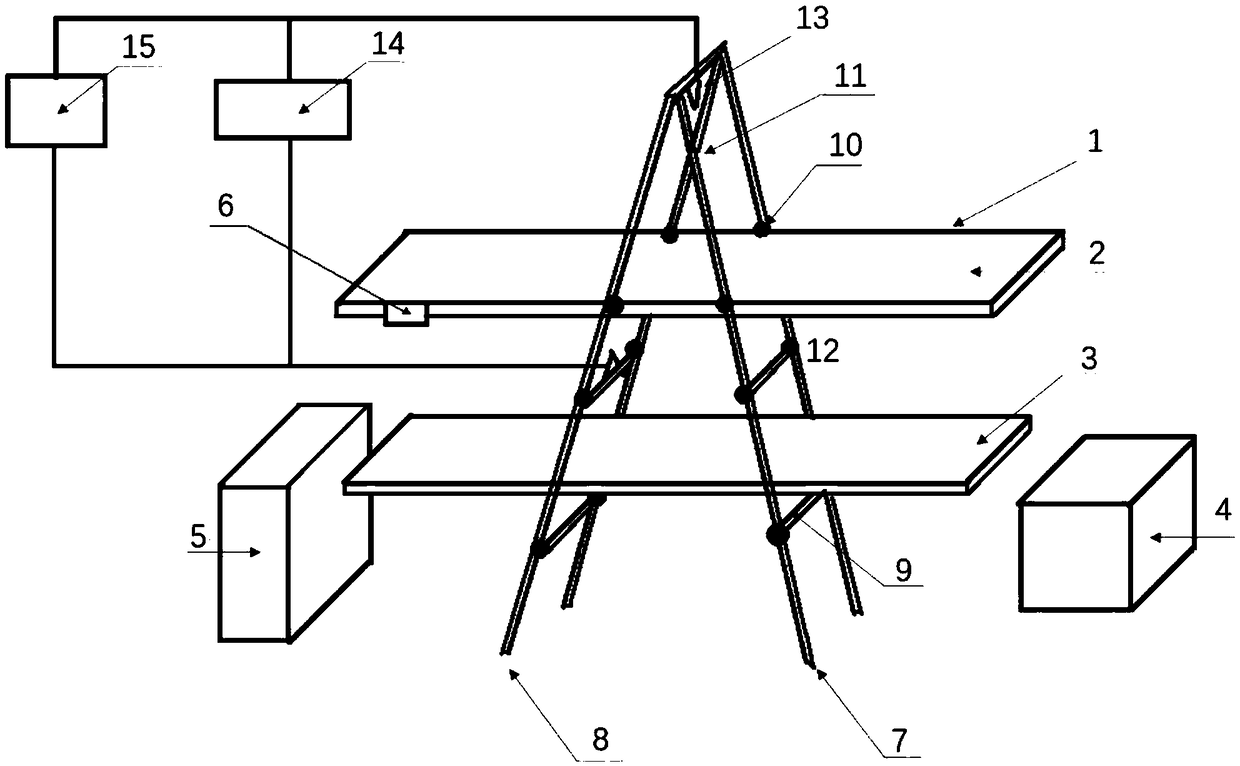
[0039] see figure 1 , figure 1 It is a schematic structural diagram of a fiber pretreatment device in Embodiment 1 of the present invention. Such as figure 1 As shown, the fiber pretreatment device includes: this embodiment provides an automatic spraying device for fiber pretreatment, including a transmission rack 1 with a length of 2-10m and a width of at least 0.2-2m. A mesh conveyor belt 2 is set, and the treatment liquid collecting plate 3 is located under the transmission rack 1, the length is at least 2-10m, and the width is at least 0.2-2m; the treatment liquid recovery container 4 is located on one side of the treatment liquid collecting plate 3, and the Fiber collection box 5 is installed under the rear end of frame 1, servo motor 6 is placed on conveying frame 1, scales are marked on front frame 7 and rear frame 8, and the height is set at least 1.5-2m. There are several crossbeams 9 and positioning holes 10 on the top, which can adjust the height of the transmiss...
Embodiment 2
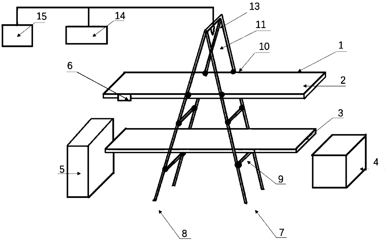
[0043] see figure 2 , figure 2 It is a schematic structural diagram of a fiber pretreatment device in Embodiment 2 of the present invention. Such as figure 2 As shown, the fiber pretreatment device includes: a transmission rack 1 with a length of 2-10m and a width of at least 0.2-2m. Below, the length is at least 2-10m, and the width is at least 0.2-2m; the treatment liquid recovery container 4 is located on one side of the collecting plate 3, the fiber collecting box 5 is installed under the rear end of the transmission frame 1, and the servo motor 6 is placed on the transmission On the frame 1, the front frame 7 and the rear frame 8 are marked with scales, and the height is at least 1.5-2m. Several beams 9 and positioning holes 10 are arranged on the front and rear frames, and the transmission frame 1 can be adjusted. and the height of the processing liquid collecting plate 3, the first spray area 11 at the cross beam 9 at the upper end of the front frame 7 is provided...
Embodiment 3
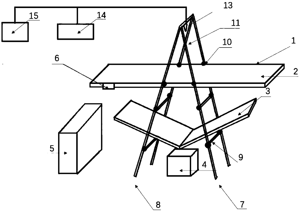
[0046] see image 3 , image 3 It is a schematic structural diagram of a fiber pretreatment device in Embodiment 3 of the present invention. Such as image 3 As shown, the fiber pretreatment device includes: a transmission frame 1 and a mesh conveyor belt 2, the length of which is at least 2-10m, and the width is at least 0.2-2m, and the "V" shaped treatment liquid collecting plate 3 is located on the transmission frame 1 The lower part is used to recover the residual treatment liquid, the length is at least 3-12m, and the width is at least 0.5-2.5m. The fiber collection box 5 is installed under the rear end of the transmission frame 1, and the servo motor 6 is placed on the transmission frame 1. The front frame 7 and the rear frame 8 are all marked with scales, and the height is at least set to 1.5-2m. Several beams 9 and positioning holes 10 are arranged on the front and rear frames, all of which can be adjusted in height. The beam 9 is the first spraying area 11, and sev...
PUM
 Abstract
Description
Claims
Application Information
 - Generate Ideas
- Intellectual Property
- Life Sciences
- Materials
- Tech Scout
- Unparalleled Data Quality
- Higher Quality Content
- 60% Fewer Hallucinations
Browse by: Latest US Patents, China's latest patents, Technical Efficacy Thesaurus, Application Domain, Technology Topic, Popular Technical Reports.
© 2025 PatSnap. All rights reserved.Legal|Privacy policy|Modern Slavery Act Transparency Statement|Sitemap|About US| Contact US: help@patsnap.com


