
Inflatable Two-Layer Fabrics By Gas

a two-layer fabric and gas technology, applied in the field of inflatable fabrics, can solve the problems of increasing manufacturing costs, complicated procedures, and weak attachment points, and achieve the effect of reducing the breathability property of the attachment area and minimizing air leakage at the attachment area

Active Publication Date: 2008-09-25
KOLON IND INC
View PDF5 Cites 4 Cited by
  • Summary
  • Abstract
  • Description
  • Claims
  • Application Information

AI Technical Summary

Benefits of technology

[0013]An object of the present invention is to solve the problems described above and to provide an inflatable fabric with an attachment area that is dense and hard such that air leakage at the attachment area can be minimized when the fabric is inflated because of remarkably lowering a breathability property of the attachment area.
[0014]Another object of the present invention is to provide an inflatable fabric having all fabric layers formed in a plain weave so that air bags with a variety of forms can be made utilizing jacquard, that is capable of being produced without a sewing process so that manufacture cost can be lowered significantly, and that has good weaving properties and smoothness.

Problems solved by technology

However, the first method for preparing the inflatable fabric by sewing, fusing with heat or microwave treatment, or adhering the two fabrics with adhesive requires additional sewing, fusing, or adhering procedures following manufacturing of the two fabrics after preparation of the textile fabric consisting of the two layers, resulting in complicated procedures and increasing manufacturing costs.
However, if they are used alone, air or gas may leak out at the attachment area, resulting in a high breathability property when the two separated layers inflate.
However, the attachment point is not strong enough because the single fabric layer (basket weave) is formed solely from one type of yarn.
If the middle of the two-layer fabric is changed into a basket pattern in order to increase strength, tension applied to the yarns at the attachment point becomes too high due to the whole attachment point consisting of the basket weave, so that weaving becomes very difficult and the shape and performance of the fabric may be negatively affected.

Method used


Image

  • Inflatable Two-Layer Fabrics By Gas
  • Inflatable Two-Layer Fabrics By Gas
  • Inflatable Two-Layer Fabrics By Gas

Examples


example 1

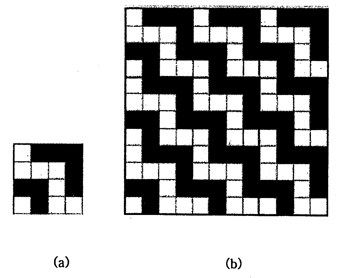
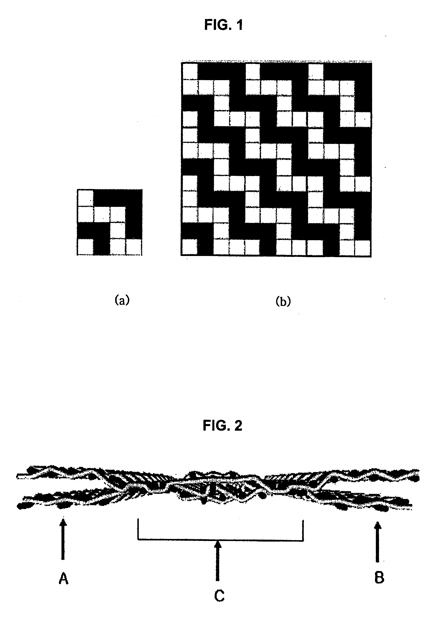
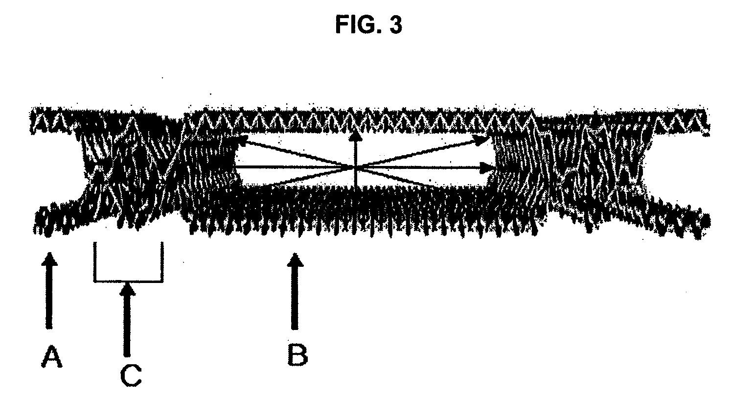
[0061]A inflatable fabric, the left separator area (A) and the right separator area (B) of which having the structure shown in FIG. 1 and FIG. 2 and being separated by the attachment area (C) which comprised 20 yarns and was formed from a combination weave pattern of a 2 / 2 basket weave pattern and a partial attaching weave of plain double weave pattern, was prepared with a jacquard weaving machine using 426-denier polyamide multifilament as warp and weft. Both the warp density and the weft density were 52 number / inch, and the cover factor was 2,131. Then, silicone rubber was coated on both sides of the inflatable fabric by a two-step coating process (coating amount: 100 g / cm2). The fabric was cut and air leakage per unit length at the attachment area, thickness of a single fabric layer, and stiffness were measured. The air leakage per unit length at the attachment area was 0.6 l / min·cm, the stiffness was 2.5 kgf, and the thickness of a single fabric layer was 0.4 mm.

example 2

[0062]A inflatable fabric, the left separator area (A) and the right separator area (B) of which having the structure shown in FIG. 1 and FIG. 2 and being separated by the attachment area (C) which comprised 20 yarns and was formed from a combination weave pattern of a 2 / 2 basket weave pattern and a partial attaching weave of a double layer weave pattern, was prepared with a jacquard weaving machine using 315-denier polyamide multifilament as warp and weft. Both the warp density and the weft density were 60 number / inch, and the cover factor was 2,129. Then, silicone rubber was coated on both sides of the inflatable fabric by a two-step coating process of undercoating and top coating (coating amount: 100 g / cm2) in order to prevent air leakage at the attachment area. The fabric was cut and air leakage per unit length at the attachment area, thickness of a single fabric layer, and stiffness were measured. The air leakage per unit length at the attachment area was 0.7 l / min cm, the stif...

example 3

[0063]A inflatable fabric was prepared in the same manner as in Example 2, except that the coating amount of silicone rubber was changed to 90 g / m2.

[0064]The thickness of a single layer of the inflatable fabric measured by the ASTM D 1777 method was 0.39 mm and the stiffness value measured by the ASTM D 4032 circular band method was 1.9 kgf. An initial pressure of 50 kPa was applied to an airbag comprising the fabric, and the inner pressure of the airbag was measured 5 seconds later at 12.5 kPa. The seam strength of the attachment area (C of FIG. 2) measured by the ASTM D 5822 method was 119 kg / in and the breaking modulus was 43%. Also, the strength maintenance ratio measured by the coating fabric wear test according to the ASTM D 4157 method was 90%. To conclude, the fabric had good installation characteristics and inflatability for use as a side curtain type of airbag.


PUM


Abstract

The present invention relates to an inflatable fabric, and more particularly to an inflatable fabric comprising two separated fabric layers which are woven at the same time using a weaving machine, and at least one an attachment area where a single layer of fabric is formed, wherein said attachment area is formed from at least a weave pattern of at least 13 yarns selected from the group consisting of a 2 / 2 basket weave pattern, a satin weave pattern, a partial attaching weave of a double layer weave pattern, and a combination thereof Since the attachment area of the inflatable fabric of the present invention comprises at least 13 yarns, air leakage can be minimized during inflation. Also, because sewing is unnecessary, manufacture cost of shock-absorbing products including an airbag can be reduced. Further, with a superior weaving property and surface smoothness, the fabric of the present invention can be utilized for shock-absorbing products when coated with synthetic resins.

Description

BACKGROUND OF THE INVENTION[0001](a) Field of the Invention[0002]The present invention relates to an inflatable fabric that can be inflated with air, and more particularly to an inflatable fabric that can be used for car airbags, life jackets, and so forth.[0003](b) Description of the Related Art[0004]An inflatable fabric can be used for car airbags, life jackets, and the like. The inflatable fabric is especially useful for a side curtain type of airbag which is unfolded at the side windowpane to protect an occupant's head from being hurt by collision with the windowpane or other structures when a car overturns in an accident. For the airbag to safely protect the occupant, it should be at an inflated state for at least 5 seconds when the car rolls over, and the inflatable fabric is useful for this purpose.[0005]In general, methods for manufacturing inflatable fabrics for car airbags are classified into: 1) a method of sewing, sewing, fusing, or adhering two fabrics; and 2) a method ...

Claims


Application Information

Patent Timeline
IPC IPC(8): B60R21/16B32B33/00
CPCB60R2021/23509Y10T428/24033D03D1/02B60R2021/23542
Inventor YOUN, JUNG-HOONKIM, KWANG-OHLEE
Owner KOLON IND INC
Learn More