
Adjustable support bracket for crane and application method of adjustable support bracket

An adjustable, crane technology, which is applied to the bottom support structure, the braking device of the lifting equipment, the load hanging element, etc., can solve the problems of being unable to effectively adapt to various terrains and the lack of stability of the crane, and achieve simple structure and operation. Convenience and the effect of reducing labor pressure

Active Publication Date: 2018-11-09
合肥市春华起重机械有限公司
View PDF6 Cites 3 Cited by
  • Summary
  • Abstract
  • Description
  • Claims
  • Application Information

AI Technical Summary

Problems solved by technology

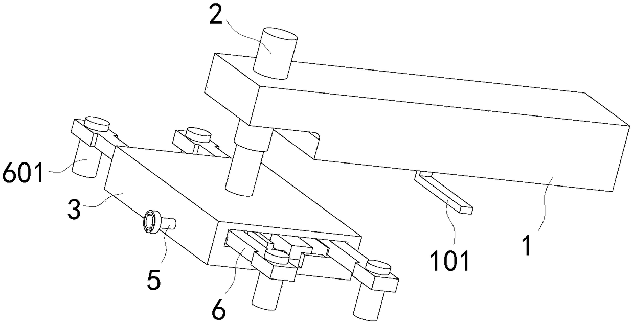
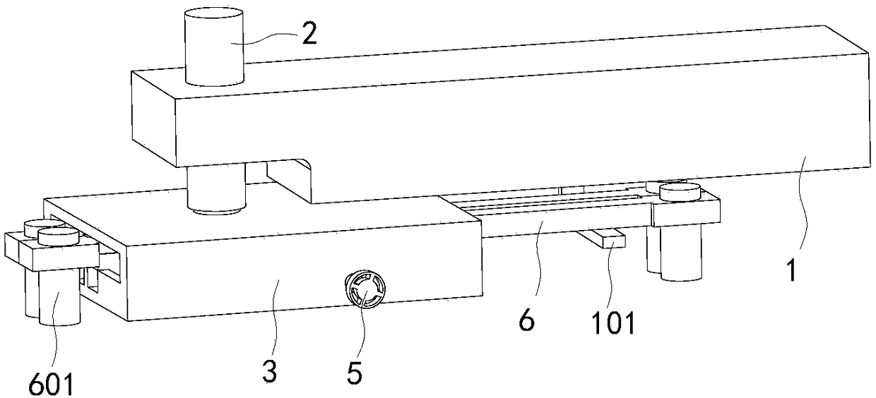
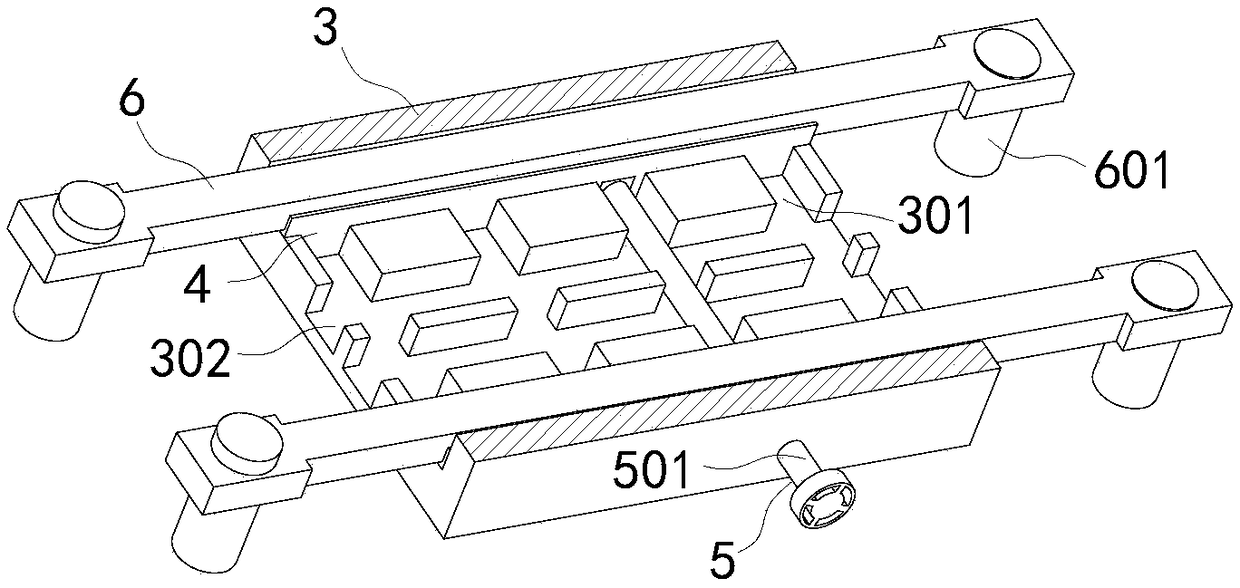
[0004] The object of the present invention is to provide an adjustable support frame for a crane and its use method, which increases the contact area between the support frame and the ground by distributing the support force of the first hydraulic cylinder to the four second hydraulic cylinders on the two support rods , improve the stability of the crane and the ability to adapt to various terrains, and solve the problem of insufficient stability of the existing cranes and the inability to effectively adapt to various terrains

Method used


Image

  • Adjustable support bracket for crane and application method of adjustable support bracket
  • Adjustable support bracket for crane and application method of adjustable support bracket
  • Adjustable support bracket for crane and application method of adjustable support bracket

Examples


Embodiment Construction

[0034] The following will clearly and completely describe the technical solutions in the embodiments of the present invention with reference to the accompanying drawings in the embodiments of the present invention. Obviously, the described embodiments are only some, not all, embodiments of the present invention. Based on the embodiments of the present invention, all other embodiments obtained by persons of ordinary skill in the art without creative efforts fall within the protection scope of the present invention.

[0035] In the description of the present invention, it should be understood that the terms "disposition", "open", "bottom surface", "top", "middle", "length", "inner wall" etc. indicate orientation or positional relationship, and are only for the purpose of It is convenient to describe the present invention and simplify the description, but does not indicate or imply that the components or elements referred to must have a specific orientation, be constructed and ope...


PUM


Abstract

The invention discloses an adjustable support bracket for a crane and an application method of the adjustable support bracket and relates to the field of hoisting equipment. The adjustable support bracket comprises a movable support leg and a first hydraulic cylinder. The first hydraulic cylinder is fixedly mounted at the end of the movable support leg. The end face of a piston rod of the first hydraulic cylinder is connected with the middle of the outer wall of the top face of an adjustment box in a rotary manner. Opposite side faces of the adjustment box are each provided with a through opening. Multiple sliding grooves are uniformly formed in the inner wall of the bottom face of the adjustment box in the width direction. Storage grooves are symmetrically formed in the middle of the bottom face of the adjustment box in the length direction, wherein the storage grooves communicate with the sliding grooves in a perpendicular manner. Two moving plates are symmetrically arranged in the sliding grooves. A transmission mechanism is mounted in one of the sliding grooves, wherein the two moving plates are controlled by the transmission mechanism to move close to or away from each other.Sliding blocks are uniformly fixed to the bottom faces of the moving plates, wherein the sliding blocks are matched with the sliding grooves in a matched manner. According to the adjustable support bracket, the support force of the first hydraulic cylinder is dispersed to four second hydraulic cylinders on two support rods so that the contact area of the support bracket and the ground can be increased, stability of the crane is improved, and adaptability, to various landforms, of the crane is improved.

Description

technical field [0001] The invention belongs to the field of hoisting equipment, and in particular relates to an adjustable support frame of a crane and a using method thereof. Background technique [0002] A crane refers to a multi-action hoisting machine that vertically lifts and horizontally transports heavy objects within a certain range, which brings great convenience to people's life and production. Therefore, the development and use of cranes in the market are becoming more and more extensive. When the crane is working, because the mechanical arm is too long, it will cause the fuselage to be unstable when lifting objects, so it is often necessary to install supporting legs on the fuselage to increase The contact area between the fuselage and the ground makes the fuselage stable. [0003] Traditional cranes use four supporting legs to contact the ground to provide stability for the crane. However, when the crane is lifting heavy objects, the supporting legs will hang ...

Claims


Application Information

Patent Timeline
Patent Type & Authority Applications(China)
IPC IPC(8): B66C5/00
CPCB66C5/00
Inventor 梁大伟
Owner 合肥市春华起重机械有限公司
Learn More