Machining device of reverse gear shaft of mini-tiller

A technology of processing device and reverse gear shaft, which is applied in positioning devices, metal processing equipment, metal processing mechanical parts, etc., can solve the problems of inability to guarantee the accuracy of the keyway, low processing efficiency of the reverse gear shaft, etc., and achieves reduced labor intensity and high precision. Effect

Pending Publication Date: 2018-11-09
重庆伦瑞风传动科技有限公司
View PDF0 Cites 3 Cited by
  • Summary
  • Abstract
  • Description
  • Claims
  • Application Information

AI Technical Summary

Problems solved by technology

[0004] Among them, the reverse gear shaft of the micro tillage machine is fixed on the inner wall of the gearbox through a key connection. In order to ensure the stability of the connection, the reverse gear shaft is provided with a plurality of key grooves along the circumference to be fixed with the inner wall of the gearbox. During processing, every time a key groove is completed Milling requires manual rotation of the reverse gear shaft and repositioning of the next keyway machining. Multiple positioning is required to process multiple keyways, which not only makes the machining efficiency of the reverse gear shaft extremely low, but also cannot guarantee the accuracy of the keyway machining

Method used


Image

  • Machining device of reverse gear shaft of mini-tiller
  • Machining device of reverse gear shaft of mini-tiller
  • Machining device of reverse gear shaft of mini-tiller

Examples


Embodiment Construction

[0029] The following is further described in detail through specific implementation methods:

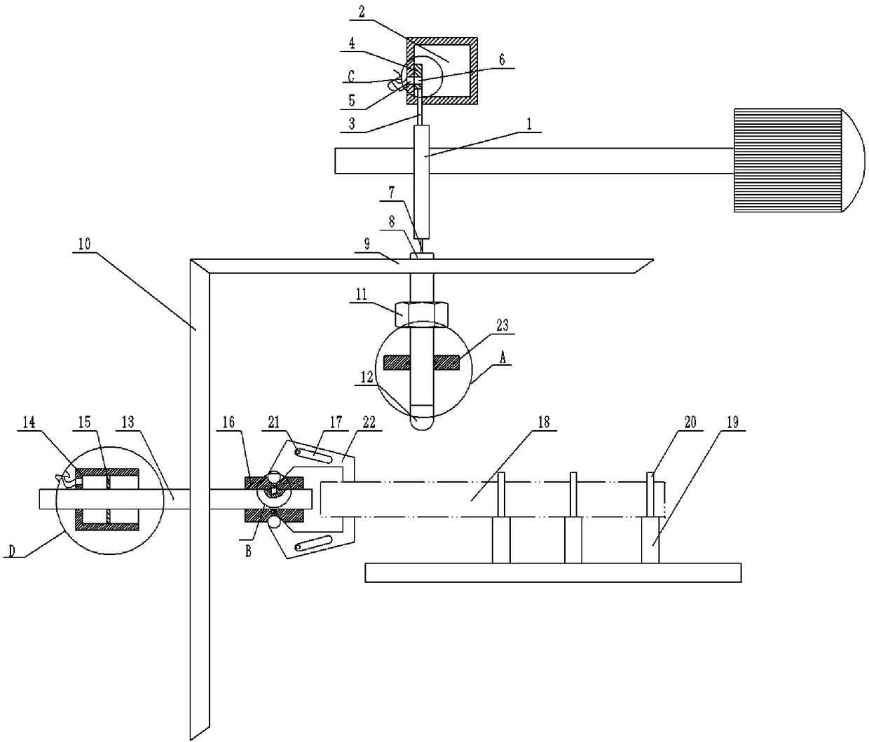
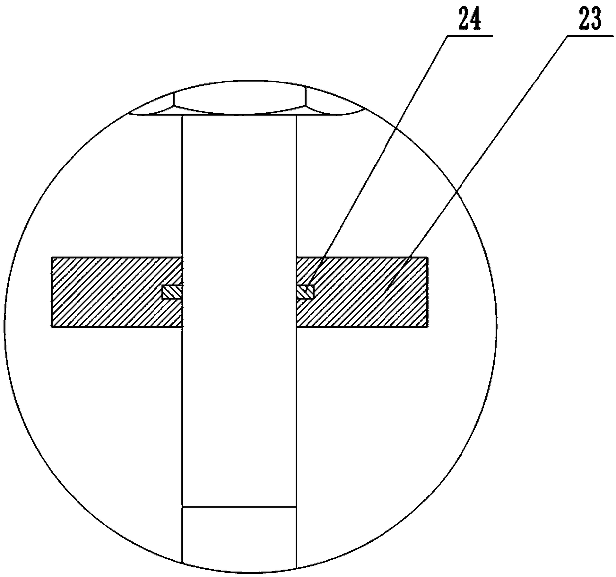
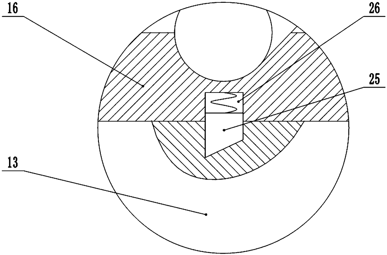
[0030] The reference signs in the drawings of the description include: cam 1, liquid storage tank 2, connecting rod 3, baffle plate 4, liquid outlet hole 5, through hole 6, slide rod 7, rotating shaft 8, first bevel gear 9, second Bevel gear 10, nut 11, milling cutter 12, clamping rod 13, piston barrel 14, piston 15, sleeve 16, bar groove 17, reverse gear shaft 18, bracket 19, placement ring 20, bump 21, jaw 22. A connecting block 23, a limiting ring 24, a wedge 25, a groove 26, a clamping block 27, and a second spring 28.

[0031] Such as figure 1 As shown, the micro tillage machine reverse shaft 18 processing device includes a frame, the frame is provided with a clamping unit, a milling unit, a cooling unit, a drying unit and a workbench, and the workbench is horizontally provided with several supports 19, combine Figure 4 As shown, the upper end of the bracket 19 is fixed with...


PUM


Abstract

The invention belongs to the field of part machining, and particularly discloses a machining device of a reverse gear shaft of a mini-tiller. A clamping unit, a milling groove unit and a worktable arearranged on a rack; the clamping unit comprises a clamping rod slidably connected to the rack; a sleeve is slidably connected to the clamping rod; a groove is formed in the inner wall of the sleeve,and a wedge block is slidably connected into the groove; a plurality of clamping claws are hinged to the sleeve in the circumferential direction; strip-shaped grooves are formed in the clamping claws;and convex blocks are fixed to the rack. The milling groove unit comprises a rotating shaft rotatably connected to the rack; the upper portion of the rotating shaft is provided with a ball thread andis in threaded connection with a nut, and the nut is fixed to the rack; a milling cutter is fixed to the lower end of the rotating shaft; a cam is rotatably connected to the rack, and the upper end of a sliding rod and the outer wall of the cam are in sliding fit; and a first bevel gear is arranged on the rotating shaft, a second bevel gear is arranged on the clamping rod, and a one-way bearing is mounted between the second bevel gear and the clamping rod. By adopting the machining device, the problem of circumferential groove milling of the reverse gear shaft of the mini-tiller is solved.

Description

technical field [0001] The invention belongs to the field of processing agricultural equipment parts, and in particular relates to a processing device for a reverse gear shaft of a tiller. Background technique [0002] Micro tillage machine has the characteristics of light weight, small size, simple structure, etc. It can travel freely in the field, and can also carry out pumping, power generation, spraying, spraying and other operations with corresponding equipment, eliminating the need for large-scale agricultural machinery to enter mountainous fields. It is the best choice to replace cattle farming in mountainous areas. [0003] The tiller gearbox is an important part of the tiller, and its performance directly affects the performance of the tiller. The structure of the gearbox assembly of the tiller is: the engine and the gearbox are directly connected through a flange, and the power is directly transmitted to the gearbox through a wet friction clutch or a cone friction...

Claims


Application Information

Patent Timeline
Patent Type & Authority Applications(China)
IPC IPC(8): B23C3/28B23Q1/25B23Q3/06B23Q11/00B23Q11/10
CPCB23C3/28B23Q1/25B23Q3/06B23Q11/005B23Q11/10
Inventor 吕新明
Owner 重庆伦瑞风传动科技有限公司
Why Eureka
Try Eureka