Drip irrigation device
A drip bottle and bottle cap technology, applied in automatic watering devices, container cultivation, gardening, etc., can solve the problems of high watering frequency, no isolation space, no moisturizing measures, etc., so as to reduce the number of watering and prevent watering. The effect of excessive water and outstanding environmental performance
- Summary
- Abstract
- Description
- Claims
- Application Information
AI Technical Summary
Problems solved by technology
Method used
Image
Examples
Embodiment approach 1
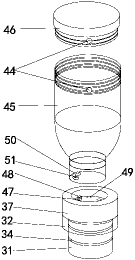
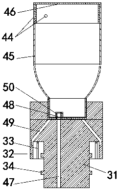
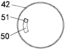
[0028] see Figure 1~Figure 4 , as can be seen from the figure, a drip irrigation device, which includes a drip bottle 41, a bottle cap 42 and a drip assembly 40 composed of a fixed part, is characterized in that the drip bottle 41 is placed upside down on the top of the fixed part, and the gap between the bottle cap 42 and the drip bottle 41 There is a threaded connection between them; the fixed part includes a circular stopper 37 and a fixed plug 31, and the circular stopper 37 is arranged on the top of the fixed plug 31; the drip bottle 41 includes a transparent bottle body 45 and a bottom screw cap 46, the transparent bottle body 45 and the bottom The screw caps 46 are threaded; the transparent bottle body 45 and the bottom screw cap 46 are provided with matching air inlets 44; the air inlets 44 can be overlapped and communicated with each other or staggered by rotating the bottom screw cap 46. Closed; the lower edge of the circular block 37 is provided with an annular col...
Embodiment approach 2
[0031] see Figure 5 , On the basis of Embodiment 1, the drip irrigation device also includes a hollow column 3 with a sealed bottom, and the outer surface of the hollow column 3 and the inner surface of the top are covered with a felt cover 35 that absorbs water and breathes; the wall of the hollow column 3 A number of evenly distributed flower insertion holes 39 are provided; the hollow column 3 is provided with a columnar absorbent sponge 36; the drip assembly 40 is arranged on the top of the hollow column 3, wherein the fixing plug 31 of the drip assembly 40 is inserted into the top of the hollow column 3 Inside, the circular block 37 of the drip assembly 40 is arranged on the top end of the hollow column 3, and the annular ferrule 32 of the drip assembly 40 is set on the felt cover 35 on the outer surface of the hollow column 3; The fixed plug 31 is a soft stripe 34 inserted in the hollow column 3 .
[0032] Hollow column 3 can be used for the climbing column of pothos 1...
Embodiment approach 3
[0034] see Figure 6~Figure 8 , on the basis of Embodiment 2, the drip irrigation device also includes a microporous disc 21 and a basin body with two layers of inner and outer layers isolated from each other; the basin body is respectively an outer basin 1 and an inner basin 2; The support ring 15, the microporous circular plate 21 is erected on the support ring 15, with the support ring 15 as the boundary, the bottom of the outer basin 1 is divided into the water storage space 7 by the microporous circular plate 21; At the central position of the microporous circular plate 21, the outer basin 1 is divided into two parts, the inner and outer parts, and the inner basin 2 is bounded by the inner planting area 8 and the ring planting area 9, which are used to accommodate different planting soils 1c; The center of the bottom of 2 is provided with an upwardly protruding column hole 22, and the hollow column 3 is arranged on the column hole 22 and the mouth of the inner basin 2 pro...
PUM
 Abstract
Description
Claims
Application Information
 - R&D
- Intellectual Property
- Life Sciences
- Materials
- Tech Scout
- Unparalleled Data Quality
- Higher Quality Content
- 60% Fewer Hallucinations
Browse by: Latest US Patents, China's latest patents, Technical Efficacy Thesaurus, Application Domain, Technology Topic, Popular Technical Reports.
© 2025 PatSnap. All rights reserved.Legal|Privacy policy|Modern Slavery Act Transparency Statement|Sitemap|About US| Contact US: help@patsnap.com


