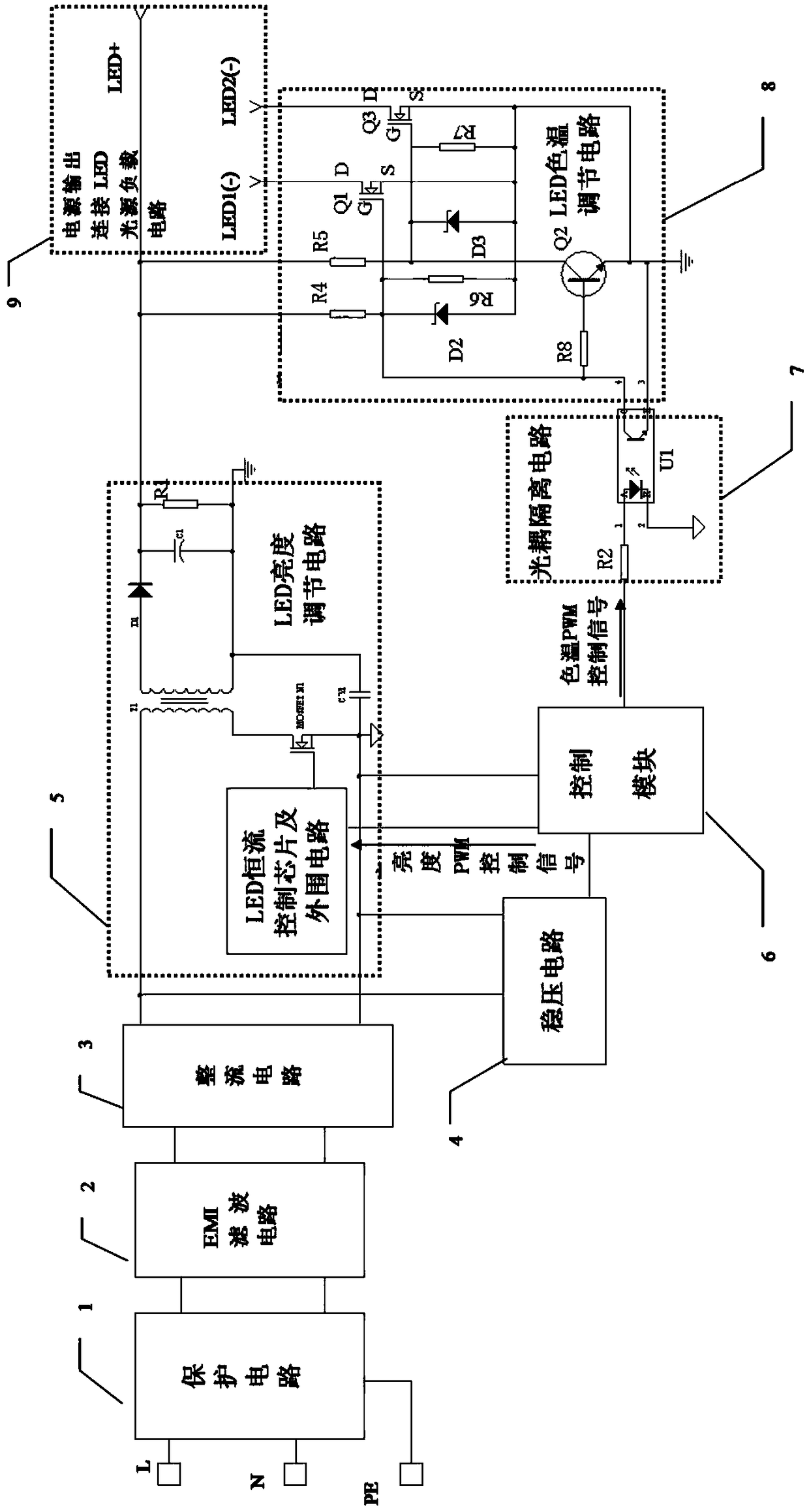
Dimming and color-regulating LED isolation constant current driving power supply
A constant current drive and power supply technology, which is applied in the field of LED dimming lighting devices, can solve the problems of failing to meet the Energy Star standard and high standby power consumption of the power supply, and achieve the effects of low power consumption, slow light decay and strong compatibility
- Summary
- Abstract
- Description
- Claims
- Application Information
AI Technical Summary
Problems solved by technology
Method used
Image
Examples
Embodiment 1
[0043] Such as figure 1 As shown, the input end of the optocoupler isolation circuit 7 receives the color temperature PWM control signal. The optocoupler isolation circuit 7 includes an optocoupler, which is denoted as the first optocoupler. The color temperature PWM control signal passes through the current limiting resistor R4, the first optocoupler U1 is isolated and transmitted to the secondary of the dimmable LED isolation drive circuit (connected to R5 and the G pole of the switch tube Q1), the C pole of the first optocoupler is connected to the LED color temperature adjustment circuit 8, and the LED color temperature adjustment circuit 8 includes the first output switch tube Q1, the second output switch tube Q3 and the triode Q2. The C pole of the first optocoupler is connected to the negative pole of the power supply end of the warm white light source through the first output switch tube Q1. The C pole of the first optocoupler After the phase inversion of the triode Q2...
Embodiment 2
[0052] Such as figure 2 As shown, the LED color temperature adjustment circuit includes the third output switch tube Q4 and the fourth output switch tube Q5, the color temperature PWM control signal includes the first color temperature PWM control signal and the second color temperature PWM control signal, and the optocoupler isolation circuit includes two optocoupler , respectively the second optocoupler U2 and the third optocoupler U3, the input end of the second optocoupler receives the first color temperature PWM control signal, the input end of the third optocoupler receives the second color temperature PWM control signal, the second optocoupler’s The C pole is connected to the negative pole of the warm white light source power supply terminal through the third output switch tube, and the C pole of the third optocoupler is connected to the negative pole of the positive white light source power supply terminal through the fourth output switch tube.
[0053] The C pole of ...
PUM
 Abstract
Description
Claims
Application Information
 - R&D
- Intellectual Property
- Life Sciences
- Materials
- Tech Scout
- Unparalleled Data Quality
- Higher Quality Content
- 60% Fewer Hallucinations
Browse by: Latest US Patents, China's latest patents, Technical Efficacy Thesaurus, Application Domain, Technology Topic, Popular Technical Reports.
© 2025 PatSnap. All rights reserved.Legal|Privacy policy|Modern Slavery Act Transparency Statement|Sitemap|About US| Contact US: help@patsnap.com


