A switch type room temperature controller

A controller and switch-type technology, applied in program control, computer control, general control system, etc., can solve problems such as large heat, insufficient battery power, and inability to collect temperature data, and achieve accurate indoor temperature and strong load compatibility. , the effect of simple wiring

Active Publication Date: 2019-06-18
HEBEI GONGDA KEYA ENERGY TECH
View PDF7 Cites 0 Cited by
  • Summary
  • Abstract
  • Description
  • Claims
  • Application Information

AI Technical Summary

Problems solved by technology

[0003] At present, the heating method in the society mostly adopts the extensive collective heating method, and the demand value of the room temperature in the household cannot be effectively collected and utilized.
At the same time, residents cannot automatically close and open the heating pipes according to their own actual conditions, resulting in the consumption of a large amount of heat when there is no need for heating at home. At the same time, the heating company cannot adjust the heating capacity according to the actual temperature value of the residents' existing houses. How much, resulting in a great waste of resources
[0004] The installation of the existing room temperature controller needs to drill another hole on the wall for fixed installation or threading, which will cause certain damage to the wall, and the wall needs to be repaired, requiring more manpower and material resources
There are also some special users who are not allowed to punch holes in the wall or other places, and can only be placed in a certain place indoors, which is easy to move. The controller closes the valve, causing the indoor temperature to be lower than the set temperature
The existing room temperature controller is powered by battery, which will cause insufficient battery power and not be replaced in time, artificially remove the battery, poor battery contact and other battery reasons, the temperature data in the room cannot be collected, the on-off controller cannot be controlled, and the control of indoor temperature regulation

Method used


Image

  • A switch type room temperature controller
  • A switch type room temperature controller
  • A switch type room temperature controller

Examples


Embodiment Construction

[0029] Specific examples of the present invention are given below. The specific embodiments are only used to further describe the present invention in detail, and do not limit the protection scope of the claims of the present application.

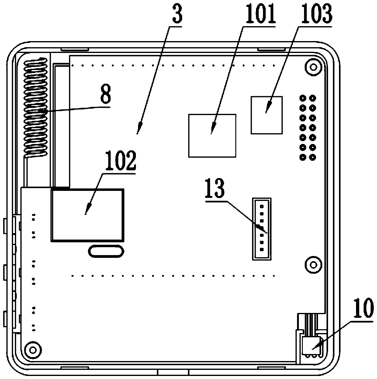
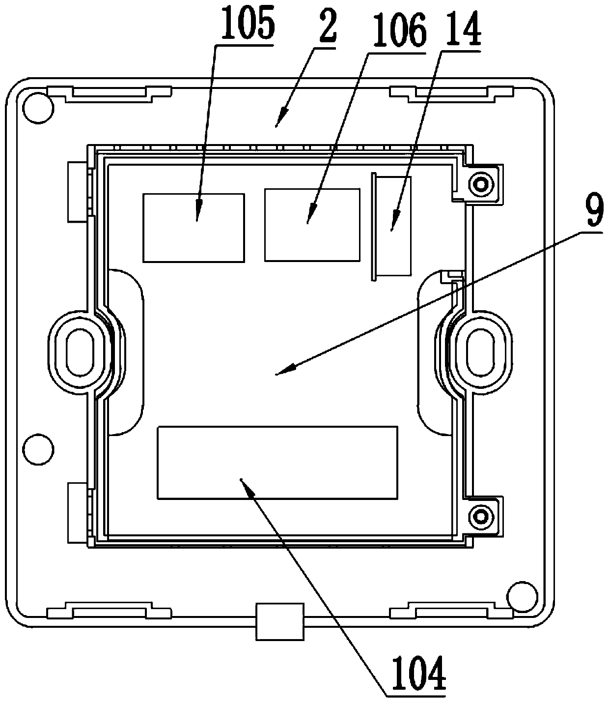
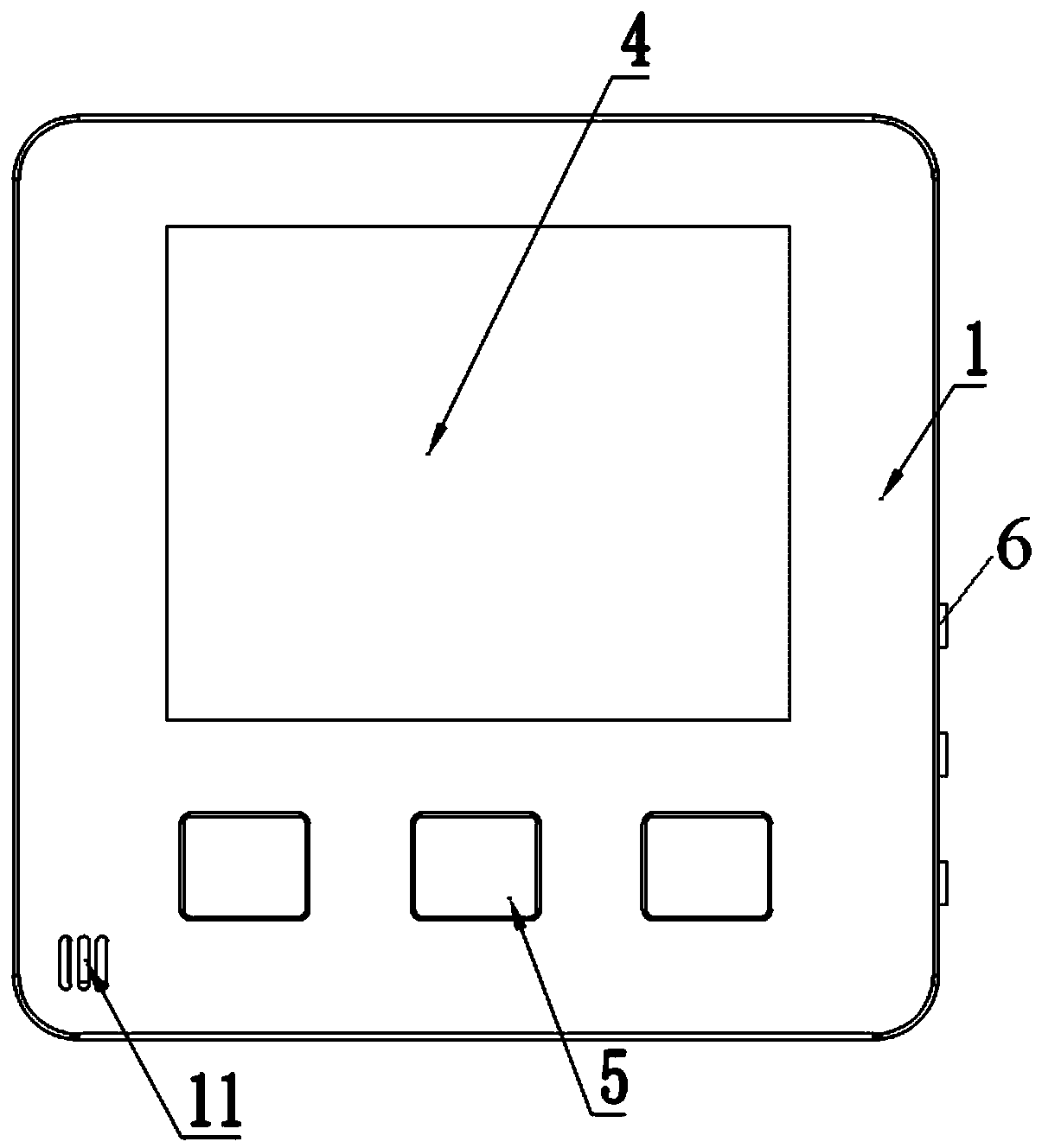
[0030] The invention provides a switch type room temperature controller (see Figure 1-9, referred to as the controller), including front cover 1, rear cover 2, temperature control board 3, display 4, temperature control button 5, light control button 6, lamp terminal 7, antenna 8, switch board 9, temperature sensor 10, the A ventilation hole 11, installation hole 12, first connector 13, second connector 14, second ventilation hole 15, MCU chip 101, wireless module 102, low power detection module 103, lamp switch module 104, single live wire power supply Conversion module 105 and power storage module 106;

[0031] The front cover 1 and the rear cover 2 are snap-connected to form the main shell of the controller; the temperature control ma...


PUM


Abstract

The invention discloses a switch-type room temperature controller. The switch-type room temperature controller comprises a front cover, a rear cover, a temperature control mainboard, a displayer, temperature control keys, lamp control keys, a lamp connection terminal, an antenna, a temperature sensor, an MCU chip, a wireless module, a low-voltage detection module, a switch mainboard, a lamp switch module, a single-firing line electricity taking conversion module and an electric quantity storage module; the temperature control mainboard is fixed into the front cover; the MCU chip, the wireless module and the low-voltage detection module are installed on the temperature control mainboard; the switch mainboard is fixed into the rear cover; the lamp switch module, the single-firing line electricity taking conversion module, the electric quantity storage module and the lamp connection terminal are installed on the switch mainboard; the temperature control mainboard is connected with the switch mainboard through a connector and the lamp connection terminal. According to the controller, electricity is taken from a single firing line to be supplied to a system, and therefore the cost of a battery is omitted; the standard 86 type wall switch appearance design is adopted, therefore, an original 86 type switch is replaced, and a lamp control switch function is achieved.

Description

technical field [0001] The invention relates to the application field of intelligent heating, in particular to a switch-type room temperature controller. Background technique [0002] In winter, central heating is adopted in the northern region to provide residents with the indoor temperature required for life. With the increase in the number of urban residential buildings in recent years and the increasing air pollution caused by factors such as heating emissions, the adoption of effective energy-saving and emission-reduction methods has become the top priority of the current heating work. [0003] At present, the heating method in the society mostly adopts the extensive collective heating method, and the demand value of the room temperature in the household cannot be effectively collected and utilized. At the same time, residents cannot automatically close and open the heating pipes according to their own actual conditions, resulting in the consumption of a large amount o...

Claims


Application Information

Patent Timeline
Patent Type & Authority Patents(China)
IPC IPC(8): G05B19/042
CPCG05B19/0423G05B2219/25257
Inventor 齐成勇吴向东余粉英高蒙
Owner HEBEI GONGDA KEYA ENERGY TECH
Why Eureka
Try Eureka