FOD (Foreign Object Debris) detection radar
A radar and base technology, applied in the field of FOD detection radar, can solve the problems of poor detection accuracy of FOD radar, achieve the effect of reducing the number of radars, suppressing ground clutter, and expanding the detection range
- Summary
- Abstract
- Description
- Claims
- Application Information
AI Technical Summary
Problems solved by technology
Method used
Image

Examples
Embodiment 1
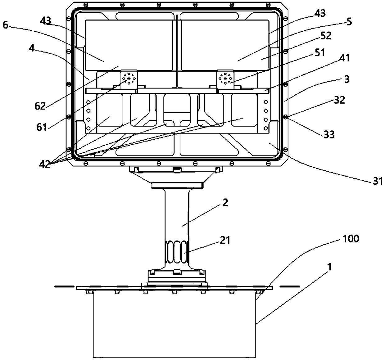
[0028] see figure 1 , a kind of FOD detection radar provided by the present invention, described detection radar comprises: base 1, is a box body, is positioned at airport runway (not shown) on the ground on both sides of the length direction outside and is provided with accommodating groove 100, so The base 1 is installed in the accommodating tank 100, and a connection hole (not shown) is opened in the middle of the upper surface of the base 1; a connecting sleeve 2 is vertically arranged on the upper surface of the base 1 and covered On the outer periphery of the connection hole of the base 1, a rotating shaft (not shown) is arranged in the middle of the inner side of the connecting sleeve 2 along the axial direction of the connecting sleeve 2. The lower end of the rotating shaft is inserted into the connecting hole of the base 1 and extends from the connecting hole. Into the inner side of the base 1; a support platform 3, shaped as a box, erected on the upper opening end of...
Embodiment 2
[0034] The support platform 3 is provided with a detection opening 31 and a cover is provided with a cover (not shown), and the surface of the cover is provided with two antenna openings (not shown) corresponding to the signal receiving antenna 5 and the signal transmitting antenna 6 respectively, A detection opening (not shown) corresponding to one of the supporting openings 42 is defined on the surface of the casing.
[0035] Further, the openings of the two antennas are respectively covered with a transparent cover (not shown).
[0036] Further, the support platform 3 is provided with a detection opening 31 and a number of installation holes 32 are spaced apart at a position close to the edge, and a number of installation through holes corresponding to the installation holes 32 are provided on the side of the cover opposite to the detection opening 31 (not shown), several locking pieces 33 are respectively inserted into the installation through holes and the installation ho...
Embodiment 3
[0040] The support plate 4 surface above the support beam 41 is provided with two support frames 43 at intervals along the length direction of the support plate 4, and the shapes of the two support frames 43 are matched with the shapes of the receiving reflection surface 52 and the emission reflection surface 62 respectively; The receiving reflective surface 52 and the emitting reflective surface 62 are respectively embedded in the support frame 43 .
[0041] The design of the support frame 43 can support and fix the receiving reflective surface 52 and the transmitting reflective surface 62 , so as to ensure the stable operation of the signal receiving antenna 5 and the signal transmitting antenna 6 .
[0042] All the other are with embodiment 1.
PUM
 Abstract
Description
Claims
Application Information
 - R&D
- Intellectual Property
- Life Sciences
- Materials
- Tech Scout
- Unparalleled Data Quality
- Higher Quality Content
- 60% Fewer Hallucinations
Browse by: Latest US Patents, China's latest patents, Technical Efficacy Thesaurus, Application Domain, Technology Topic, Popular Technical Reports.
© 2025 PatSnap. All rights reserved.Legal|Privacy policy|Modern Slavery Act Transparency Statement|Sitemap|About US| Contact US: help@patsnap.com