Optical pulse sensor of intelligent water meter

A smart water meter and sensor technology, applied in the direction of instruments, measuring devices, measuring flow/mass flow, etc., can solve the problems of high-frequency scanning, high power consumption, high power consumption of water meter sensors, and increased pointer rotation resistance. Effective sensing area, reduced overall operating power consumption, and reduced operating time

Pending Publication Date: 2018-11-06
ZHIHENG TECH CO LTD
View PDF10 Cites 5 Cited by
  • Summary
  • Abstract
  • Description
  • Claims
  • Application Information

AI Technical Summary

Problems solved by technology

Among them, the magnetic induction water meter sensor needs to install a magnetic flow pointer in the water meter body; the flow collection device needs to integrate a magnetic sensitive element to detect the flow collection of the water meter; therefore, the magnetic induction water meter sensor has the following defects: it is necessary to install a magnetic The pointer has an attractive effect on the metal water meter body, which will increase the rotation resistance of the pointer and affect the performance of the water meter
[0003] Camera direct-reading water meters use a camera to take photos of the readings on the dial and upload them to the background for background software recognition or manual recognition. However, the use of camera direct-reading water meters has the following defects: the amount of image data is too large, and network transmission is difficult; cost Higher, difficult to promote; camera power is higher, cannot support real-time monitoring, can only replace manual reading of water meter dial numbers regularly, and cannot monitor the flow process of water meters in real time
However, the LC metal induction sensor has the following defects: since the resonant waveform amplitude of the LC is affected by the metal sheet pointer approaching the LC resonant circuit, the distance between the metal sheet pointer and the LC resonant circuit is required to be relatively close, which makes the requirements for the structure of the water meter more complex. Harsh, can only be aimed at specialized water meter bodies, therefore, the versatility is poor
However, the two photosensitive electronic components in this scheme need to be close together so that there is an overlapping sensing area; since the photosensitive area is small, it is necessary to determine whether the water meter pointer rotates to th...

Method used


Image

  • Optical pulse sensor of intelligent water meter
  • Optical pulse sensor of intelligent water meter
  • Optical pulse sensor of intelligent water meter

Examples


Embodiment Construction

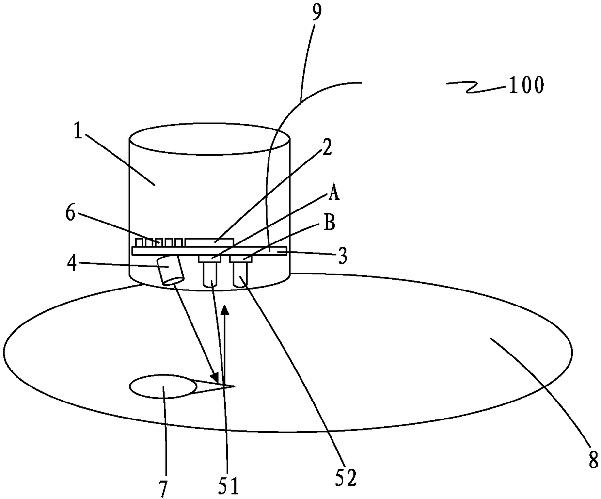
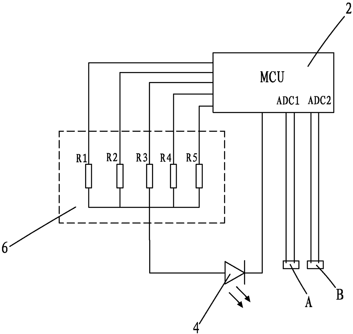
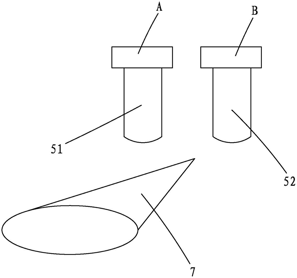
[0028] Please refer to Figure 1 to Figure 3As shown, an optical pulse sensor 100 of a smart water meter in the present invention, the optical pulse sensor 100 includes a sensor housing 1, an MCU 2, a circuit board 3, a light emitting diode 4, and two optical environment brightness sensing elements A, B , two light guide columns 51, 52 and a current limiting resistor unit 6; the MCU2 and the circuit board 3 are all located inside the sensor housing 1, the MCU2 is fixed on the circuit board 3, specifically the MCU2 can be fixed On the upper surface of the circuit board 3; the MCU2 is connected to the positive pole of the light-emitting diode 4 through the current-limiting resistor unit 6, and the negative pole of the light-emitting diode 4 is connected to the MCU2. In specific implementation, it can be The light-emitting brightness of the light-emitting diode 4 is controlled by the current-limiting resistor unit 6, and the larger the resistance value, the darker the light-emitt...


PUM


Abstract

The invention provides an optical pulse sensor of an intelligent water meter. The optical pulse sensor comprises a sensor shell body, a MCU (Microprogrammed Control Unit), a circuit board, a light-emitting diode, optical environment brightness induction elements, light guide columns and a current-limiting resistance unit, wherein the MCU and the circuit board are arranged in the sensor shell body;the MCU is fixed on the circuit board; the MCU is connected with the light-emitting diode through the current-limiting resistance unit; the light-emitting diode is connected with the MCU; the opticalenvironment brightness induction elements are connected with the MCU; the optical environment brightness induction elements are arranged at the bottom of the circuit board at interval; the light guide columns are fixedly arranged on the lower surfaces of the optical environment brightness induction elements; the light-emitting diode is obliquely arranged at the bottom of the circuit board; lightspots, which are irradiated to an index dial by the light-emitting diode, are located just below the two light guide columns. The optical pulse sensor of the intelligent water meter, provided by the invention, has the advantages that the power consumption of the operation of a whole body can be extremely reduced so that the requirements on lower power consumption of the intelligent water meter when a battery is used for supplying power can be met very well.

Description

technical field [0001] The invention relates to the field of intelligent water meters, in particular to an optical pulse sensor of an intelligent water meter. Background technique [0002] In the smart water meter industry, the existing water meter flow acquisition sensors mainly include the following types: magnetic induction water meter sensor, camera direct reading water meter, LC metal induction sensor and light sensing water meter sensor. Among them, the magnetic induction water meter sensor needs to install a magnetic flow pointer in the water meter body; the flow collection device needs to integrate a magnetic sensitive element to detect the flow collection of the water meter; therefore, the magnetic induction water meter sensor has the following defects: it is necessary to install a magnetic The pointer has an attractive effect on the metal water meter body, which will increase the rotation resistance of the pointer and affect the performance of the water meter. [...

Claims


Application Information

Patent Timeline
IPC IPC(8): G01F1/66
CPCG01F1/661G01F1/662
Inventor 杨荣锦李贵生林开荣周春辉谢远勇代艳
Owner ZHIHENG TECH CO LTD
Why Eureka
Try Eureka