
Hydraulic winch driving mechanism

A driving mechanism, hydraulic technology, applied in hoisting device, clockwork mechanism, etc., can solve the problems of large safety accidents of reducers, low efficiency of judging fault points, and only shutdown for replacement, so as to reduce procurement costs and benefit Effect of individual control and redundant design, shortening procurement cycle

Active Publication Date: 2018-11-06
LIAONING FUWA HEAVY IND MACHINERY
View PDF5 Cites 0 Cited by
  • Summary
  • Abstract
  • Description
  • Claims
  • Application Information

AI Technical Summary

Problems solved by technology

Once damaged, it can only be replaced by stopping the machine
Moreover, in the hydraulic system, for a multi-motor parallel system, without a control valve, the efficiency of judging the fault point is relatively low
In this way, in a large and important hoisting environment, once a component fails, the construction progress of each link will be delayed
Moreover, the damage of the reducer will cause a great safety accident, and the maintenance and replacement must be under no-load conditions, which is very difficult

Method used


Image

  • Hydraulic winch driving mechanism
  • Hydraulic winch driving mechanism
  • Hydraulic winch driving mechanism

Examples


Embodiment Construction

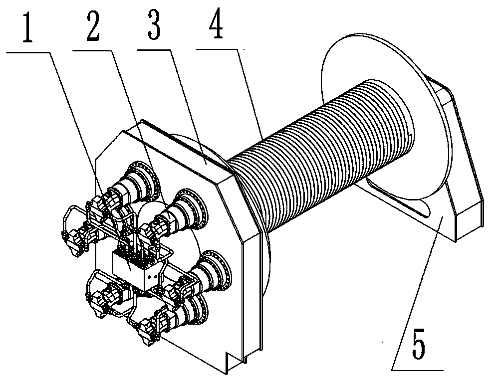
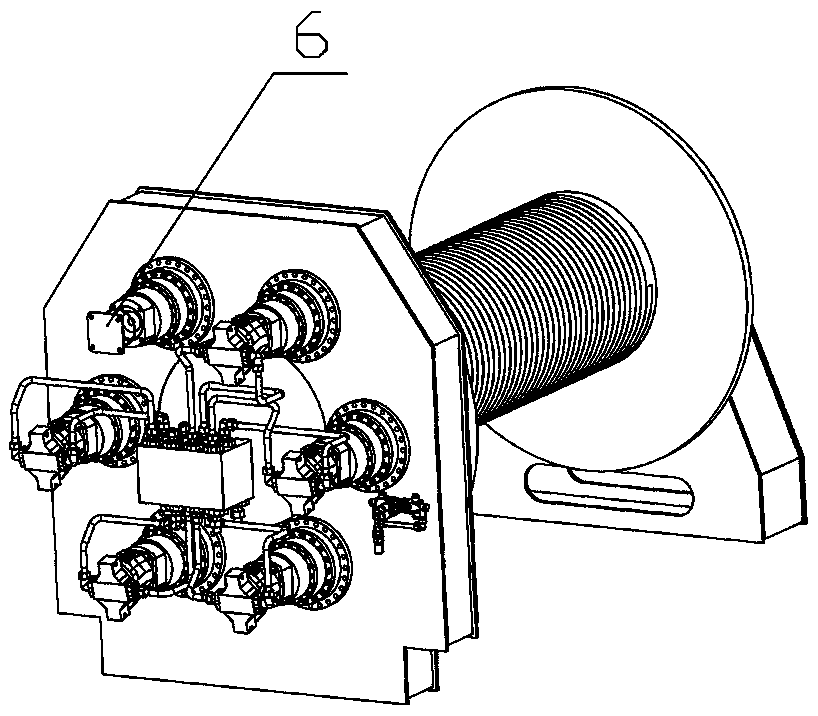
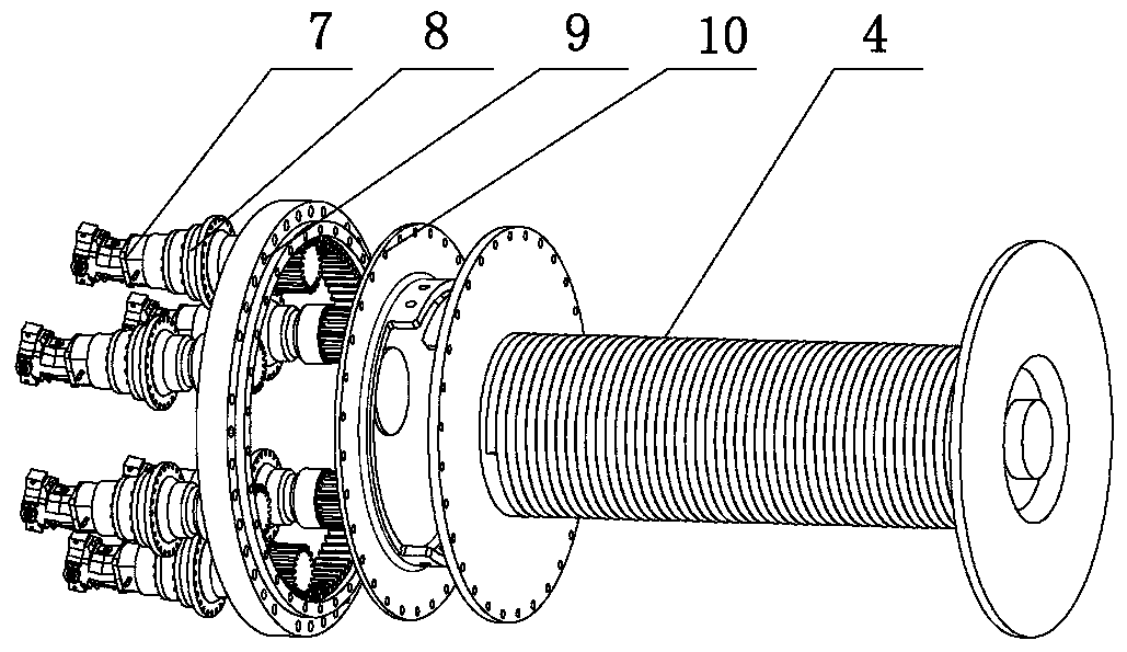
[0015] Before the implementation of the present invention, it is necessary to calculate the overall torque, select models according to parameters, and match the number of local drives (including actual drives and backup drives). The hydraulic winch driving mechanism is composed of a hydraulic control valve 1 , a driving unit 2 , a structural frame 3 , a reel 4 , a bearing bracket 5 , and a blocking element 6 . The hydraulic motor 7 and the reducer 8 are installed together to form an independent drive unit 2, and the reducer 8 is inserted into the structural frame 3 on the driving side of the reel 4; there is a rotary roller 9 inside the structural frame 3, and each drive unit decelerates The shaft head gear of machine 8 meshes with the internal teeth of the large ring gear of the rotary roller 9, and the large ring gear of the rotary roller 9 drives the adapter plate 10 fixedly connected with the reel 4 driving side plates to rotate.

[0016] The drive units fixed on the struc...


PUM


Abstract

The invention relates to a hydraulic winch driving mechanism of a crane. The hydraulic type winch driving mechanism mainly comprises hydraulic motors, speed reducers, a rotary rolling disc, a windingdrum and a structural frame of the winding drum, a bearing seat support and a hydraulic control system. According to the hydraulic winch driving mechanism, the plurality of sets of hydraulic motors and speed reducers are adopted for driving, and small gears of the speed reducers are meshed with a large gear ring of the rotary rolling disc to transfer torque; each group of the speed reducer and thehydraulic motor serves as a driving unit, and the plurality of driving units are uniformly distributed on the circumference of the large gear ring of the rotary rolling disc; a standby unit can be additionally arranged through the driving mechanism, and the driving mechanism has the advantage that when a certain unit breaks down, the fault unit is removed firstly, and a new driving unit can be intervened; and the driving units are controlled by a control valve, and intelligent switching can be realized according to the form of the fault; and the hydraulic control winch driving mechanism has redundant design.

Description

technical field [0001] The invention belongs to the technical field of cranes, and in particular relates to a hydraulically controlled winch driving mechanism. Background technique [0002] The hoist is the main torque outputter on the crane. According to different functions, it mainly includes lifting hoist and luffing hoist. The hoisting of traditional small cranes only needs to meet the output torque of the wire rope, and the matching is mature. Both imported and domestic components are used, and the requirements for the procurement cycle and timeliness of maintenance are relatively low. But today, with the increasing development of large-scale equipment hoisting, the construction party has extremely strict requirements on the reliability of operation and use, timeliness of troubleshooting, and spare parts cycle of large-scale lifting equipment above 1,000 tons. [0003] At present, in the hoist design of large cranes, due to the large pulling force of the single rope an...

Claims


Application Information

Patent Timeline
Patent Type & Authority Applications(China)
IPC IPC(8): B66D1/08B66D1/44B66D1/28
Inventor 魏太有魏文儒逄广思于双豪李建徐宏高延庆刘相阳
Owner LIAONING FUWA HEAVY IND MACHINERY
Learn More