
Surface polishing machining equipment

A processing equipment and surface polishing technology, applied in metal processing equipment, grinding/polishing equipment, manufacturing tools, etc., can solve the problems of low production efficiency, difficult quality control, high defect rate, and achieve the effect of uniform grinding and flexible grinding

Inactive Publication Date: 2018-11-06
FOSHAN CITY NANHAI POPULA FAN
View PDF6 Cites 1 Cited by
  • Summary
  • Abstract
  • Description
  • Claims
  • Application Information

AI Technical Summary

Problems solved by technology

[0002] Due to the rapid development of robots and electric vehicles, the demand for electric motors is increasing. The production of existing electric motors is labor-intensive, which causes manufacturers to bear high labor costs, and manual operations often lead to difficult quality control and production. inefficiency
[0003] The motor shaft of the motor is often the first step in motor processing, and the positioning hole on the end face of the motor shaft is the benchmark for subsequent processing. Therefore, the end face processing of the motor shaft requires high precision. The existing manual processing has a very high defect rate. height of

Method used


Image

  • Surface polishing machining equipment

Examples


Embodiment Construction

[0012] The idea, specific structure and technical effects of the present invention will be clearly and completely described below in conjunction with the embodiments and accompanying drawings, so as to fully understand the purpose, features and effects of the present invention. Apparently, the described embodiments are only some of the embodiments of the present invention, rather than all of them. Based on the embodiments of the present invention, other embodiments obtained by those skilled in the art without creative efforts belong to The protection scope of the present invention. In addition, all the connection / connection relationships mentioned in this article do not refer to the direct connection of components, but mean that a better connection structure can be formed by adding or reducing connection accessories according to specific implementation conditions. The various technical features in the present invention can be combined interactively on the premise of not confli...


PUM


Abstract

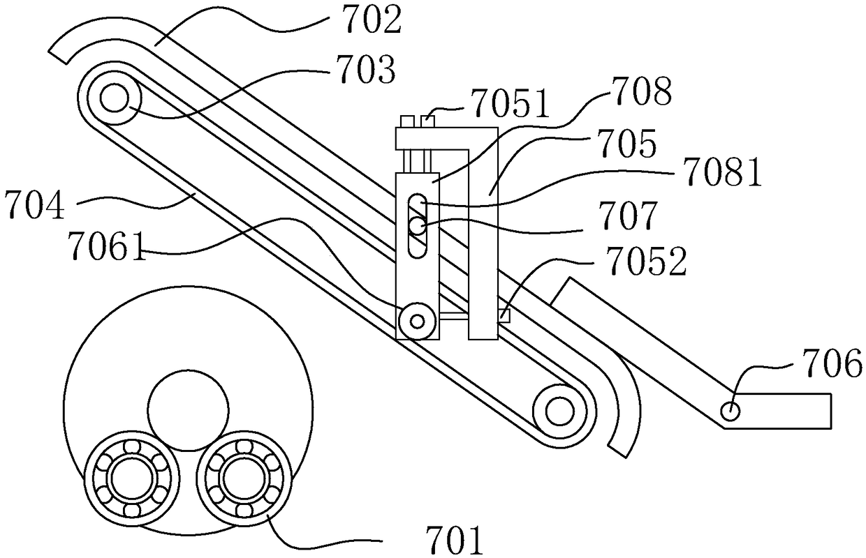
The invention discloses surface polishing machining equipment. The surface polishing machining equipment comprises a polishing machine body provided with a support shaft assembly. The support shaft assembly comprises bearing sets. Each bearing set comprises support shaft bearings. A convolution space is arranged between the two bearing sets. A polishing assembly is arranged on the rear side of thesupport shaft assembly and comprises a polishing base frame provided with two abrasive belt wheels, wherein an abrasive belt is in winding connection to the two abrasive belt wheels, and the polishing base frame can drive the abrasive belt to swing up and down around a work rotation shaft. During usage, a rotor is placed on the support shaft assembly, a rotor core is arranged in the convolution space, a drive motor is started, the abrasive belt rotates, then, the polishing base frame is made to swing downwards, and the abrasive belt conducts polishing and grinding on the rotor core. The abrasive belt is soft so that large-area, rapid and soft grinding can be well conducted; and the rotor can be driven to rotate through rotation of the abrasive belt, and accordingly uniform grinding is conducted on the peripheral face of the rotor core. The surface polishing machining equipment is used for motor shaft machining.

Description

technical field [0001] The invention relates to motor shaft processing equipment, in particular to surface polishing processing equipment. Background technique [0002] Due to the rapid development of robots and electric vehicles, the demand for motors is increasing. The production of existing motors is labor-intensive, which leads to high labor costs for manufacturers, and manual operations often lead to difficult quality control and production. The problem of inefficiency. [0003] The motor shaft of the motor is often the first step in motor processing, but the positioning hole on the end face of the motor shaft is the benchmark for subsequent processing, so the end face processing of the motor shaft requires high precision, and the existing manual processing has a very high defect rate. height of. In the automatic production process, after the motor shaft with the end face is grabbed from the CNC machining machine, the motor shaft needs to be positioned before the auto...

Claims


Application Information

Patent Timeline
Patent Type & Authority Applications(China)
IPC IPC(8): B24B21/02B24B21/18B24B21/22
Inventor 唐秀文徐永森肖洪斌
Owner FOSHAN CITY NANHAI POPULA FAN
Learn More