Welding frame of spot welding machine

A technology of spot welding machine and welding frame, which is applied in the direction of welding equipment, welding equipment, resistance welding equipment, etc., can solve the problems of not conforming to modern industrial production, high labor intensity of workers, low welding pass rate, etc., and achieve spot welding welding process The effect of stability, simple structure and low input cost

Inactive Publication Date: 2018-11-06
河北小蜜蜂工具集团有限公司
View PDF7 Cites 1 Cited by
  • Summary
  • Abstract
  • Description
  • Claims
  • Application Information

AI Technical Summary

Problems solved by technology

The disadvantages of this method are: low efficiency, high labor intensity, low welding qualification rate, poor stability, and does not meet the characteristics of modern industrial production.

Method used


Image

  • Welding frame of spot welding machine
  • Welding frame of spot welding machine
  • Welding frame of spot welding machine

Examples


Embodiment

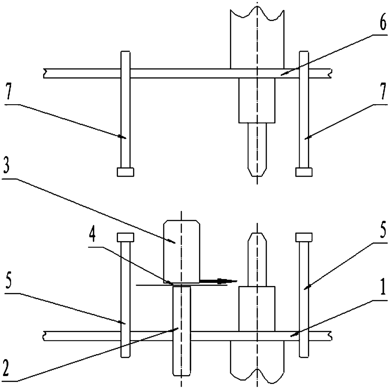
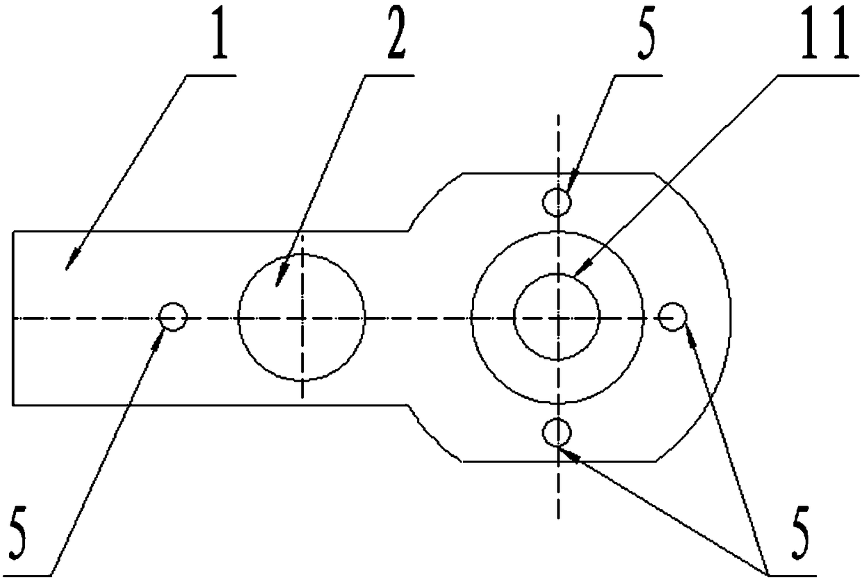
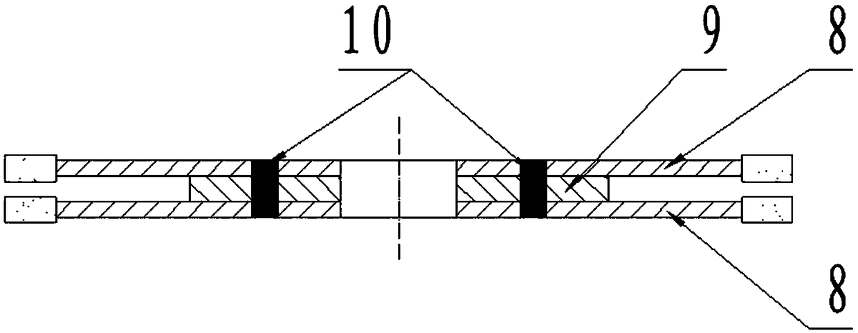
[0038] The present invention comprises a lower base 1 , a support column 2 , a rotating fixed shaft 3 , a dial 4 , a lower pressing block 5 , an upper base 6 , and an upper pressing block 7 . Both the lower base 1 and the upper base 6 are made of tool steel, the lower base 1 is fixed on the lower welding head 11 of the spot welding machine; the upper base 6 is fixed on the upper welding head of the spot welding machine; the support column 2 is installed on the lower base 1 , can adjust the distance with the upper welding head, and can fix the position; the rotating fixed shaft 3 is made of insulating bakelite, is coaxially connected with the support column 2 through the bearing, and can rotate freely; the dial 4 is fixed on the rotating fixed shaft 3, record the rotation angle of the rotating fixed shaft 3; the lower pressing block 5 and the upper pressing block 7 are both made of high elastic rubber and stainless steel columns, the lower pressing block 5 is installed on the lo...

example 1

[0056] The product Φ125D produces double-layer slotted pieces, the thickness of the middle welding piece is 2.0mm, and the outer diameter of the welding piece is Φ65mm. A total of 105 pieces are required to be produced. Debug the equipment according to the drawings and process requirements, and start spot welding. It took a total of 1.5 hours. After inspection, there were no defective products such as weak welding and deviation of solder joints. There was no deviation in the depth and size of solder joints, and the pass rate was 100%. The production test proves that the equipment of the invention can fully meet the needs of batch production, and the equipment input cost is low and the efficiency is high.


PUM


Abstract

The invention discloses a welding frame of a spot welding machine, and belongs to the field of manufacturing of diamond tools. The welding frame of the spot welding machine comprises an upper weldingframe body and a lower welding frame body, wherein an upper welding head of the spot welding machine is sleeved with the upper welding frame body and the lower welding frame body. The lower welding frame body is provided with a rotary fixing shaft arranged at the center of a circular saw blade in a sleeved mode and a plurality of lower pressing blocks supporting the periphery of the circular saw blade. The upper welding frame body is provided with upper pressing blocks which are located over the lower pressing blocks and abut against the circular saw blade. The welding frame is an indispensable auxiliary device of the diamond circular saw blade used for spot-welding production. Transition from manual operation to stable mechanical production is achieved. The welding frame is simple in structure and low in investment cost. The welding frame makes the spot welding process more stable and is easy to operate, capable of achieving firm spot welding, attractive and suitable for volume production.

Description

technical field [0001] The invention belongs to the field of diamond tool manufacturing, and relates to a welding frame of a spot welding machine. Background technique [0002] Diamond circular saw blades are made of diamond particles, metal matrix and matrix, which are sintered as a whole. It is mainly used for cutting or grinding hard and brittle materials such as stone, marble, ceramic tile, microcrystalline stone, concrete, etc. It is one of the commonly used hardware tools. [0003] In the case of special requirements such as cutting objects, cutting equipment, and cutting methods, it is necessary to thicken the base of the diamond circular saw blade, or use multiple diamond circular saw blades in combination. At present, the most commonly used processing method is to use a spot welding machine to spot weld on the substrate, so as to obtain a thicker substrate or special-shaped products. The advantages of using the spot welding method are: compared with the direct use...

Claims


Application Information

Patent Timeline
Patent Type & Authority Applications(China)
IPC IPC(8): B23K11/11B23K11/36B23K37/04B23D65/00
CPCB23D65/00B23K11/11B23K11/36B23K37/0408
Inventor 彭乃聪董小雷张翠芳冯景
Owner 河北小蜜蜂工具集团有限公司
Why Eureka
Try Eureka