
Preparation method of catalyst for removing ammonia nitrogen in landfill leachate by electrolyzing and electrolyzing device thereof.

A technology of landfill leachate and electrolysis device, which is applied in the field of catalyst preparation and electrolysis device for electrolyzing landfill leachate to remove ammonia nitrogen, which can solve the problems of poor ammonia nitrogen removal effect, improve safety and stability, accelerate oxidation efficiency, and high removal rate effect

Inactive Publication Date: 2018-11-06
中科海创环境科技(大连)有限公司
View PDF6 Cites 3 Cited by
  • Summary
  • Abstract
  • Description
  • Claims
  • Application Information

AI Technical Summary

Problems solved by technology

[0006] In order to solve the problem of poor removal effect of ammonia nitrogen in landfill leachate, the present invention proposes a method for preparing a catalyst for electrolyzing landfill leachate to remove ammonia nitrogen. The catalyst prepared by the preparation method performs electrolytic catalytic oxidation on landfill leachate, which can improve the ammonia nitrogen The removal rate

Method used


Image

  • Preparation method of catalyst for removing ammonia nitrogen in landfill leachate by electrolyzing and electrolyzing device thereof.

Examples


Embodiment 1

[0028] A preparation method of a catalyst for removing ammonia nitrogen from electrolytic landfill leachate, including the following steps:

[0029] Step 1: Grind the activated carbon powder through a 100-mesh screen, boil the activated carbon powder under the sieve in deionized water for 30 minutes and then cool, and repeat the sieving, boiling and cooling operations 3 times.

[0030] Step 2: Dry the activated carbon powder obtained in Step 1 at a temperature of 105-115°C until the activated carbon powder has a constant weight.

[0031] Step 3: Place the activated carbon powder obtained by drying in step 2 in the ferric chloride immersion solution for continuous stirring, soak until the adsorption is saturated, discard the supernatant, and wash the activated carbon with deionized water for 3 times at 105-115°C Dry for 24 hours under conditions to obtain metal-loaded activated carbon. Specifically, the volume ratio of the activated carbon powder to the ferric chloride impregnation so...

Embodiment 2

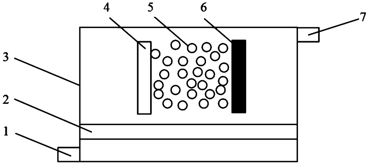
[0035] See attached figure 1 , An electrolysis device for electrolyzing a catalyst for removing ammonia and nitrogen from landfill leachate, comprising a reaction housing 3, a cathode plate 6 and an anode plate 4 in the reaction housing 3, and the catalyst for removing ammonia and nitrogen from the electrolytic landfill leachate described in Example 1. Preparation method prepared catalyst 5. The reaction shell 3 is made of insulating and pressure-resistant composite material. The area ratio of the cathode plate 6 and the anode plate 4 is 1:1, and the spacing is 2 cm. The reaction shell 3 is connected with a water inlet pipe 1 and a water outlet pipe 7, the water inlet pipe 1 communicates with the lower part on one side of the reaction shell 3, and the water outlet pipe 7 communicates with the upper part on the other side of the reaction shell 3 . An aeration pipe 2 is provided in the reaction shell 3. The aeration pipe 2 is arranged in the lower part of the reaction shell 3...


PUM


Abstract

The invention provides a preparation method of a catalyst for removing ammonia nitrogen in landfill leachate by electrolyzing and an electrolyzing device thereof. The method comprises the steps of soaking an activated carbon powder in a metal dipping solution; adsorbing; and then sintering with clay to form a metal-loading catalyst. The catalyst is capable of increasing the oxidization efficiencyof the electrolyzing device, so that ammonia nitrogen can be conveniently removed, and the removing rate is beyond 85%. The electrolyzing device comprises a reaction housing, a negative plate arrangedin the reaction housing, a positive plate arranged in the reaction housing, and the catalyst prepared by the abovementioned method. The electrolyzing is capable of completely and catalytically oxidizing, adsorbing and filtering the landfill leachate, so that the water quality of the leachate can be improved.

Description

Technical field [0001] The invention relates to a preparation method of a catalyst for removing ammonia nitrogen from an electrolytic garbage leachate and an electrolysis device thereof. Background technique [0002] Landfill leachate is a kind of liquid with high concentration of organic or inorganic components produced by the biochemical degradation of garbage during the process of stacking and landfilling due to compaction and fermentation. Simply put, it is the contaminated liquid that leaks from the garbage. water. In the process of landfilling and stacking garbage, atmospheric precipitation (rain and snow) will fall on the garbage. In addition, the garbage itself contains water, and the organic matter in the garbage will be biochemically decomposed to produce water. The above water has been leached. Garbage becomes sewage, also called landfill leachate. [0003] The water quality of landfill leachate is complex, with a wide variety of pollutants, high ammonia nitrogen and C...

Claims


Application Information

Patent Timeline
Patent Type & Authority Applications(China)
IPC IPC(8): B01J23/72B01J23/745C02F1/461C02F101/16
CPCC02F1/46104B01J23/72B01J23/745C02F2101/16B01J35/33
Inventor 郭光刘兴革王英健张欣欣尹伟
Owner 中科海创环境科技(大连)有限公司
Learn More