
Conveying device and developing machine

A transmission device and developing machine technology, applied in photography, optomechanical equipment, optics, etc., can solve problems such as poor developing effect, affecting developing effect, insufficient removal of unexposed photoresist, etc., to improve uniformity and promote uniformity Effect

Inactive Publication Date: 2018-11-02
SHENZHEN CHINA STAR OPTOELECTRONICS TECH CO LTD
View PDF6 Cites 0 Cited by
  • Summary
  • Abstract
  • Description
  • Claims
  • Application Information

AI Technical Summary

Problems solved by technology

In the current mainstream spray (SPRAY) development process, the developer is fully sprayed onto the exposed photoresist through the nozzle for development, and the developer is easy to foam; in addition, when the photoresist is developed, when air enters the developer, it will Microscopic bubbles are produced to form foam
The residual foam will block the contact between the developer and the photoresist, resulting in insufficient removal of the unexposed photoresist and poor development effect, thus affecting the integrity and fineness of the wiring
In order to suppress the side effects caused by foam, adding a defoamer to the developer is a common defoaming method at present. However, during the use of the defoamer, the resist will be continuously dissolved, and long-term use will affect the development effect.

Method used


Image

  • Conveying device and developing machine
  • Conveying device and developing machine
  • Conveying device and developing machine

Examples


Embodiment Construction

[0025] In order to further illustrate the technical means adopted by the present invention and its effects, the following describes in detail in conjunction with preferred embodiments of the present invention and accompanying drawings.

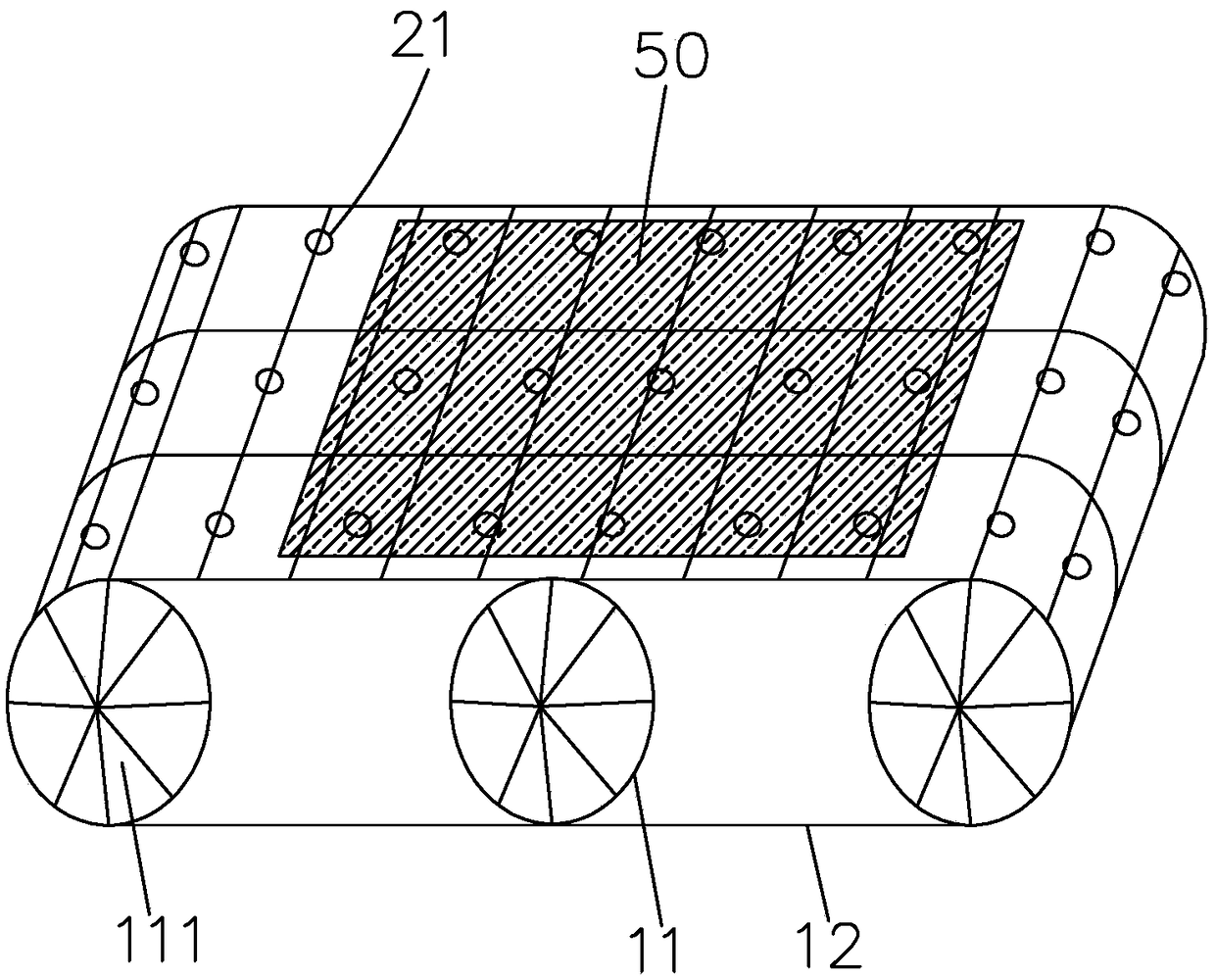
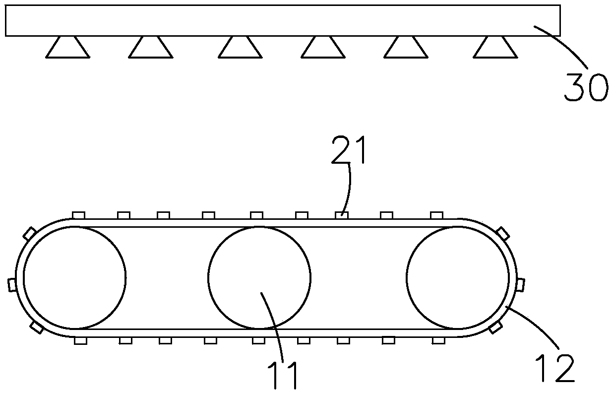
[0026] see figure 1 , the present invention firstly provides a conveying device for transferring a substrate 50 in a developing machine. A plurality of ultrasonic support protrusions 21 on the

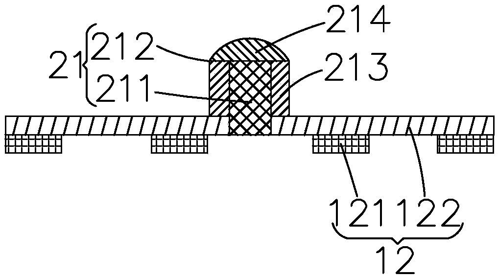
[0027] Among them, such as figure 2 As shown, each ultrasonic support protrusion 21 includes an ultrasonic vibrator 211 and a support cover 212 covering the ultrasonic vibrator 211 on the conveyor belt 12, and the ultrasonic support protrusion 21 is used as a defoaming component for eliminating bubbles in the developer;

[0028] During the process of transporting the substrate 50, the substrate 50 is supported by the ultrasonic support protrusion 21 and is in contact with the ultrasonic support protrusion 21. The ultrasonic support protrusion 21 emi...


PUM

PropertyMeasurementUnit
diameteraaaaaaaaaa
diameteraaaaaaaaaa

Abstract

The invention provides a conveying device and a developing machine. The conveying device comprises a conveying roller group, a conveying belt arranged on the conveying roller group in a sleeved mode and a plurality of ultrasonic supporting bulges uniformly arranged on the conveying belt; each ultrasonic supporting bulge comprises an ultrasonic vibrator and a supporting cover body which covers theultrasonic vibrator on the conveying belt; in a process of conveying a substrate, the ultrasonic supporting bulges send out ultrasonic waves through the ultrasonic vibrators, wherein the substrate issupported by the ultrasonic supporting bulges in a contact mode, so that when the substrate is conveyed on the conveying belt, the ultrasonic supporting bulges can enable a developing liquid on the substrate to be in the ultrasonic environment, bubbles in the developing liquid can be removed in real time, and meanwhile the distribution uniformity of the developing liquid on the substrate is promoted, thereby improving the developing capacity uniformity of developing liquid. The developing machine provided by the invention comprises the conveying device; by virtue of the developing machine, bubbles in the developing liquid can be removed in real time, the distribution uniformity of the developing liquid on the substrate is promoted, and therefore, the uniformity of developing capability ofthe developing liquid can be improved.

Description

technical field [0001] The invention relates to the field of display technology, in particular to a conveying device and a developing machine. Background technique [0002] In the field of display technology, flat-panel displays such as Liquid Crystal Display (LCD) and Organic Light Emitting Diode (OLED) displays have gradually replaced CRT displays, and are widely used in LCD TVs, mobile phones, personal digital assistants, digital Cameras, computer or laptop screens, etc. [0003] The display panel is an important part of LCD and OLED. Whether it is an LCD display panel or an OLED display panel, it usually has a thin film transistor (Thin Film Transistor, TFT) substrate. Taking the LCD display panel as an example, it is mainly composed of a TFT substrate, a color filter (CF) substrate, a liquid crystal layer and a sealant (Sealant) arranged between the two substrates, and its molding process generally includes: the front section Array (Array) process (thin film, yellow ...

Claims


Application Information

Patent Timeline
Patent Type & Authority Applications(China)
IPC IPC(8): G03F7/30
CPCG03F7/3014G03F7/3057
Inventor 涂乐志
Owner SHENZHEN CHINA STAR OPTOELECTRONICS TECH CO LTD
Learn More