
Direct type backlight module and display terminal

A backlight module, direct type technology, applied in optics, nonlinear optics, instruments, etc., can solve problems such as the inability to achieve thinning of the TV and the overall thickness of the backlight module.

Pending Publication Date: 2018-11-02
HISENSE VISUAL TECH CO LTD
View PDF0 Cites 8 Cited by
  • Summary
  • Abstract
  • Description
  • Claims
  • Application Information

AI Technical Summary

Problems solved by technology

[0005] This application provides a direct-type backlight module and a display terminal to solve the technical problem that the current backlight module is relatively thick and cannot realize the thinning of the TV

Method used


Image

  • Direct type backlight module and display terminal
  • Direct type backlight module and display terminal
  • Direct type backlight module and display terminal

Examples


Embodiment 1

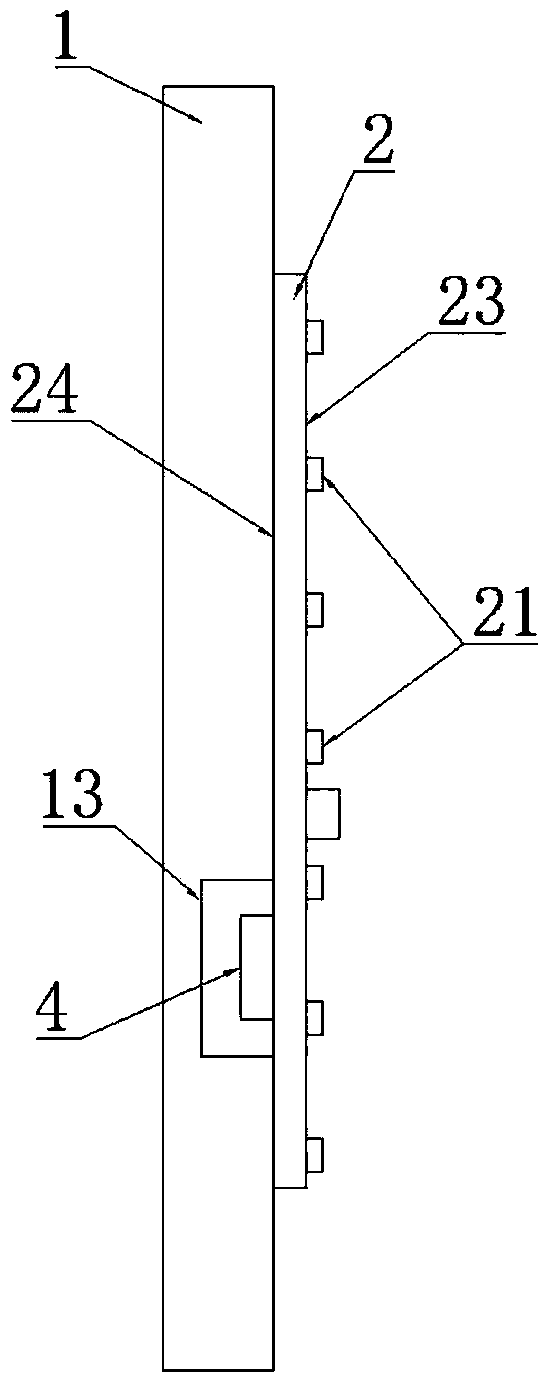
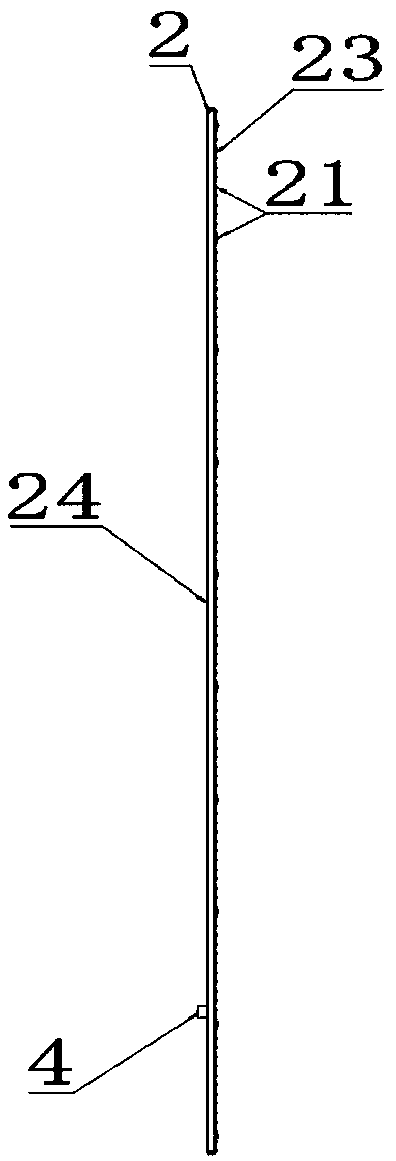
[0035] Such as figure 2 As shown, the direct-lit backlight module provided by the embodiment of the present application includes a lamp panel 2, and the first surface 23 of the lamp panel 2 is provided with LED lamps 21 arranged in an array, as shown in image 3 , Figure 4 As shown; the second surface 24 of the lamp board 2 is provided with the wiring terminal 4 of the LED lamp 21, as Figure 5As shown, the LED lamp 21 is electrically connected to the wiring terminal 4, and the wiring terminal 4 is used for external electrical connection, wherein the first surface 23 and the second surface 24 of the lamp board 2 are two opposite surfaces of the lamp board 2 .

[0036] In the direct type backlight module, the wiring terminals 4 are arranged on the second surface 24 of the lamp board 2 , so that the integration of the LED lamp 21 and the wiring terminals 4 is realized. Specifically, the wire terminal 4 integrated with the LED lamp 21 is electrically connected to the LED lam...

Embodiment 2

[0048] The direct-lit backlight module provided in the embodiment of the present application includes a lamp panel 2, and the first surface 23 of the lamp panel 2 is provided with LED lamps 21 arranged in an array, such as Figure 9 As shown; the second surface 24 of the lamp board 2 is provided with the wiring terminal 4 of the LED lamp and the lamp board driving module 22, as Figure 10 As shown; the LED lamp 21 is electrically connected to the wiring terminal 4 and the lamp board driving module 22, and the wiring terminal 4 is used for external electrical connection, wherein the first surface 23 and the second surface 24 are the opposite two sides surface.

[0049] In the direct type backlight module, the wiring terminal 4 and the lamp board driving module 22 are simultaneously arranged on the second surface 24 of the lamp board 2 , realizing the integration of the LED lamp 21 , the wiring terminal 4 and the lamp board driving module 22 . Specifically, the wiring terminal ...


PUM

PropertyMeasurementUnit
Thicknessaaaaaaaaaa

Abstract

The invention discloses a direct type backlight module and a display terminal. The backlight module comprises a lamp panel and a rear panel, wherein LED (Light Emitting Diode) lamps, which are distributed in an array, are arranged on a first surface of the lamp panel; cabling terminals and / or lamp panel driving modules of the LED lamps are arranged on a second surface of the lamp panel; the LED lamps are electrically connected with the cabling terminals and the lamp board driving modules; the cabling terminals are used for outward electric connection; the rear panel is located at the side of the second surface of the lamp panel; the rear panel is provided with an avoiding structure; the cabling terminals and the lamp panel driving modules are located in the avoiding structure. According tothe direct type backlight module disclosed by the invention, the cabling terminals and the lamp panel driving modules are arranged on one surface of the lamp panel and are stored in the avoiding structure of the rear panel, so that the LED lamps and the cabling terminals and / or the lamp panel driving modules are integrated and the area ratio of a function panel on the rear panel is reduced so that the appearance region of the rear panel is enlarged; the rear panel can be used as a rear shell, so that the thickness of the backlight module is greatly reduced and a television is thinned.

Description

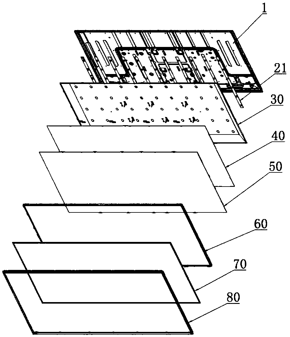
technical field [0001] The present application relates to the technical field of liquid crystal televisions, in particular to a direct-lit backlight module and a display terminal. Background technique [0002] LCD TVs are widely used because of their wide color gamut, long service life, environmental protection and energy saving, and ultra-thin appearance. Due to the wide use of LCD TVs, the competition among various businesses is becoming more and more fierce. The pursuit of ultra-thin appearance has become a means of competition for various businesses. . [0003] Such as figure 1 It is a structural schematic diagram of an existing direct-lit LCD TV. A traditional direct-lit LCD TV includes a backlight module, a liquid crystal panel 70 arranged in the light emitting direction of the backlight module, and a plastic frame 60 and a front frame for sandwiching the liquid crystal panel 70 80. The backlight module includes a backplane 1, a reflector 30, a diffusion plate 40, a ...

Claims


Application Information

Patent Timeline
IPC IPC(8): G02F1/13357
CPCG02F1/133603G02F1/133608G02F1/133612
Inventor 唐志强韩建国马骥陈宇
Owner HISENSE VISUAL TECH CO LTD
Learn More