
An ethane recovery method suitable for rich gas with absorption tower

A recovery method and absorption tower technology, which is applied in the field of gas-rich ethane recovery, can solve the problems of reduced turbine expansion gas phase, high energy consumption of refrigeration compressors, and increased external compression work, so as to increase turbine expansion The effect of improving the recovery rate of ethane and reducing the heat transfer load

Active Publication Date: 2019-05-03
SOUTHWEST PETROLEUM UNIV
View PDF1 Cites 2 Cited by
  • Summary
  • Abstract
  • Description
  • Claims
  • Application Information

AI Technical Summary

Problems solved by technology

[0004] In the ethane recovery process for relatively rich gas, part of the dry gas recirculation process adopts primary cooling, the feed gas is pre-cooled in the cold box and then directly enters the low-temperature separator, and a large amount of methane enters the demethanizer after condensing in the low-temperature separator In the middle of the tower, resulting in an increase in the separation load of the demethanizer
One-stage separation makes the refrigerant need to cool all the raw material gas, the refrigerant circulation is large, and the energy consumption of the refrigeration compressor is high
The first-stage separation will also reduce the separated gas phase in the low-temperature separator, and at the same time, a part of the separated gas phase in the low-temperature separator needs to be cryogenically cooled by the cold box to provide materials for the upper absorption section of the demethanizer to improve the recovery rate. The amount of gas phase in flat expansion decreases, the expansion work of the turbine decreases, and the external compression work increases

Method used


Image

  • An ethane recovery method suitable for rich gas with absorption tower
  • An ethane recovery method suitable for rich gas with absorption tower
  • An ethane recovery method suitable for rich gas with absorption tower

Examples


Embodiment 1

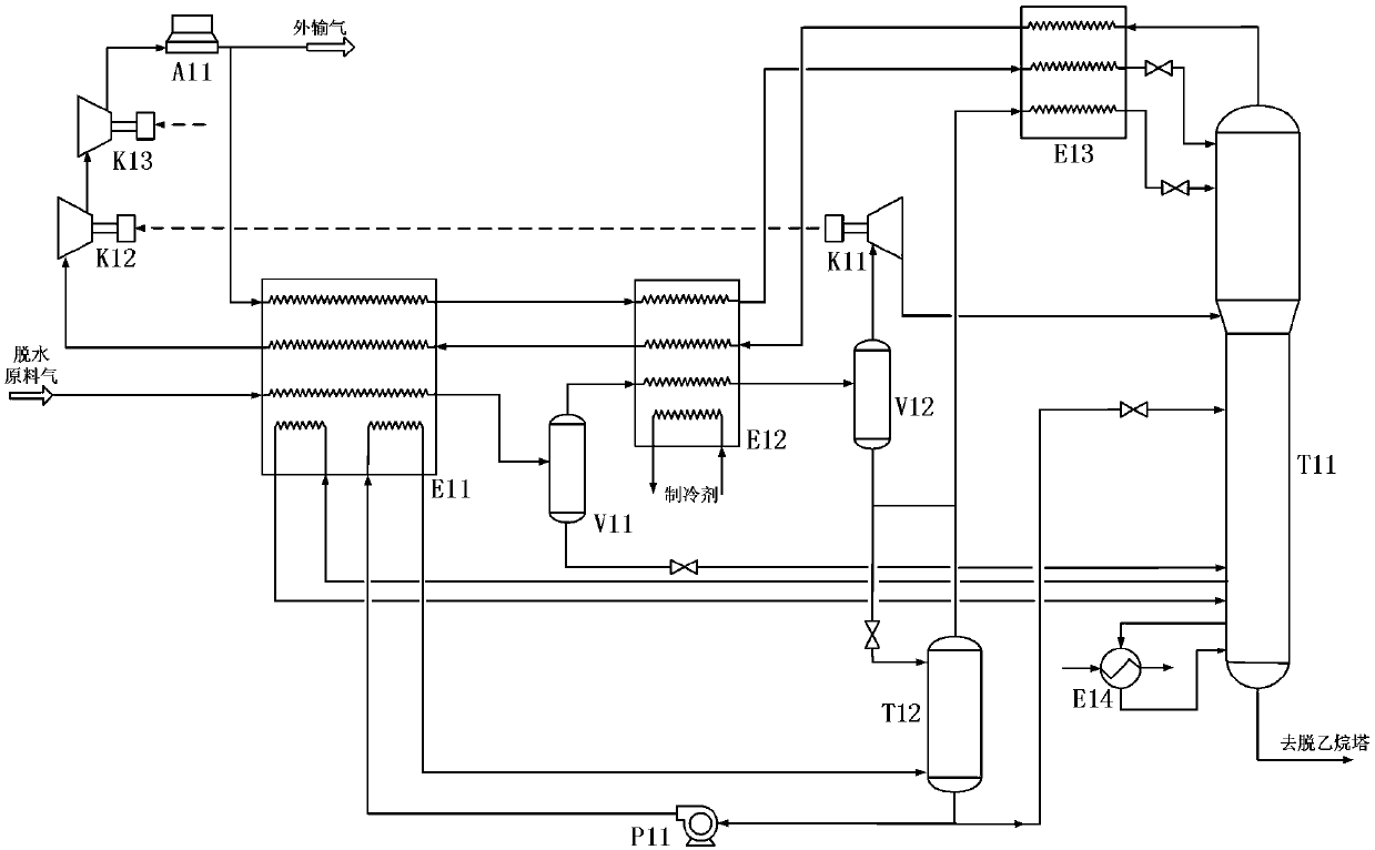
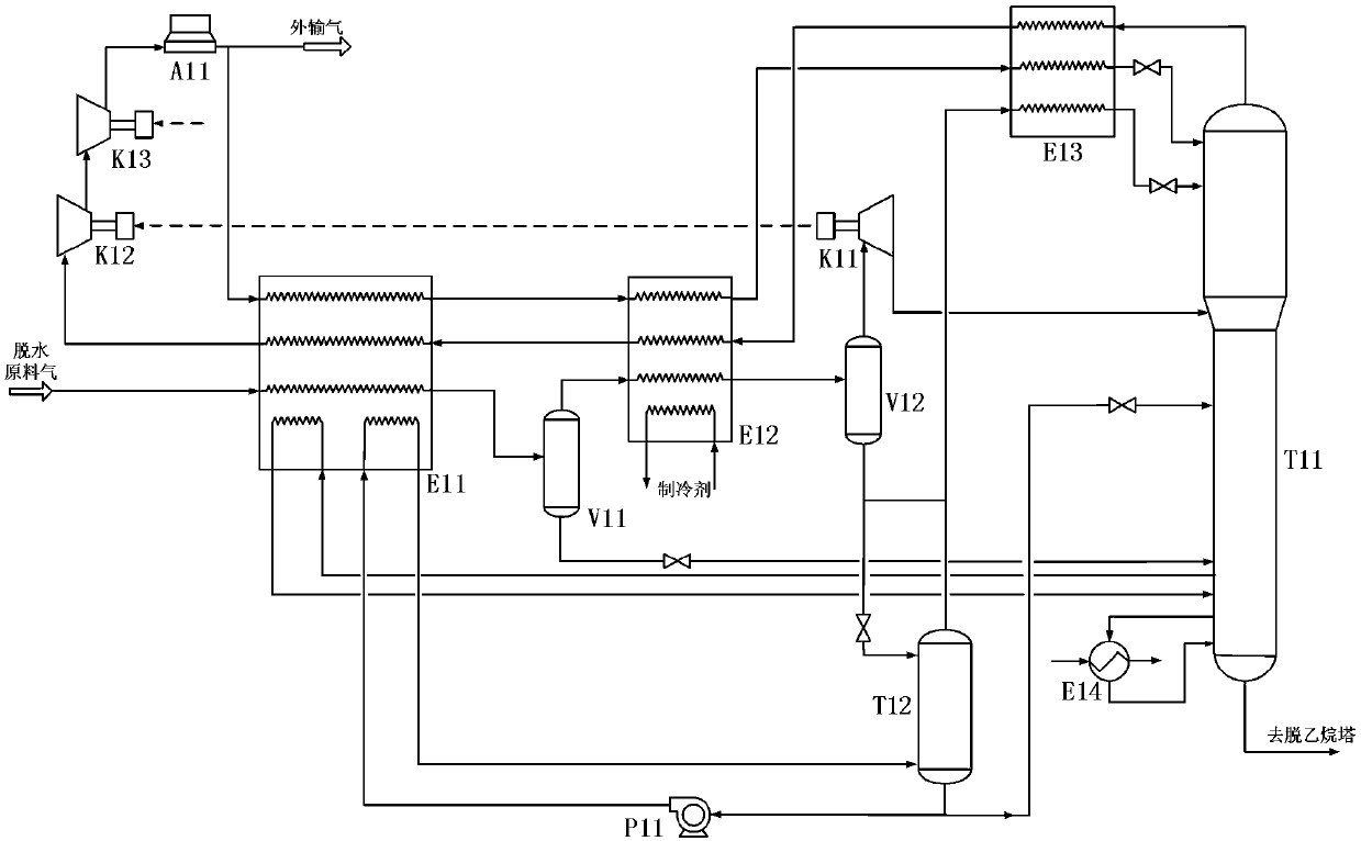
[0024] Such as figure 1 As shown, the composition and working conditions of 4 feed gas are as follows:

[0025] Raw material gas treatment scale: 500×104m 3 / d

[0026] Raw gas pressure: 5.5MPa

[0027] Raw gas temperature: 38°C

[0028] Dry gas output pressure: 5.5MPa

[0029] The raw gas composition is shown in Table 1

[0030] Table 1 Feed gas composition

[0031] composition

N 2

CO 2

C 1

C 2

C 3

iC 4

c 4

iC 5

c 5

C 6

mol%

1.24

1.04

72.77

14.29

7.55

0.73

1.84

0.23

0.21

0.1

[0032] Such as figure 1As shown, the present invention discloses an enhanced ethane recovery process with an absorption tower. The feed gas (5.5MPa, 38°C) is cooled by the first cold box E11 and then enters the separator V11 for pre-separation to separate the ethane in the feed gas. Some heavy hydrocarbons are used to reduce the heat exchange load in the second cold box E12. The gas phase (5.48...


PUM


Abstract

The invention discloses an ethane recovery method with an absorption tower suitable for rich gas. Raw material gas is cooled by a first cold box and then enters a separator for pre-separation; a gas phase separated by the separator enters a second cold box and is further cooled and then enters a low temperature separator; a gas phase separated by the low temperature separator totally enters the expansion end of a turbo-expander for expansion cooling, and then enters the middle-upper part of a demethanizer, a part of condensate of the bottom of the absorption tower is reheated in the first coldbox and is gasified in a large amount mode and then enters the bottom portion of the absorption tower, and the other part of the condensate is directly connected into the middle of the demethanizer;the gas phase of the top of the absorption tower is discharged and deep-cooled, and then is subjected to throttling and cooling to enter the upper portion of the demethanizer; the gas phase of the topof the demethanizer is subjected to heat transfer and heating and pressurization, and then transported outwards after cooled by an air cooler; and a condensate product at the bottom of the demethanizer enters subsequent fractionation processing units such as the demethanizer for processing. The tower overhead feed enriched with more methane can enable a better absorbing and cooling effect on theupper portion of the demethanizer, and the recovery rate of the ethane is improved.

Description

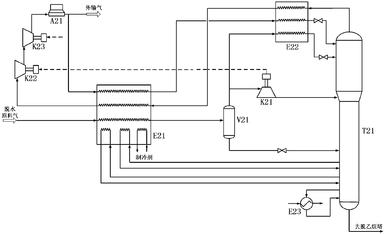
technical field [0001] The invention relates to the technical field of natural gas processing technology, in particular to an ethane recovery method with an absorption tower suitable for rich gas. Background technique [0002] As domestic oil and gas fields gradually realize the huge economic value brought by ethane products, the research and development of efficient ethane recovery process has become particularly important. At present, the most typical ethane recovery process is the partial dry gas recirculation (RSV) process. When recovering ethane from relatively rich natural gas, refrigerant auxiliary refrigeration is usually required to increase the ethane recovery rate. Partial dry gas recirculation process suitable for gas-rich ethane recovery such as figure 2 As shown, the characteristics of the process are that after dehydration, the raw material gas enters the cold box for pre-cooling and then enters the low-temperature separator. The separated liquid hydrocarbon...

Claims


Application Information

Patent Timeline
Patent Type & Authority Patents(China)
IPC IPC(8): F25J3/06F25J5/00
CPCF25J3/064F25J5/00F25J3/0209F25J3/0233F25J3/0238F25J2200/04F25J2200/70F25J2200/76F25J2205/04F25J2235/60F25J2240/02F25J2270/90
Inventor 蒋洪张世坚朱聪
Owner SOUTHWEST PETROLEUM UNIV
Learn More