A reciprocating air pump and its control method
A reciprocating air pump technology, applied in pump control, pump testing, electrical components, etc., can solve the problem of reciprocating air pumps not working, and achieve the effect of simple external line connection, good flexibility, and high energy conversion efficiency
- Summary
- Abstract
- Description
- Claims
- Application Information
AI Technical Summary
Problems solved by technology
Method used
Image
Examples
Embodiment 1
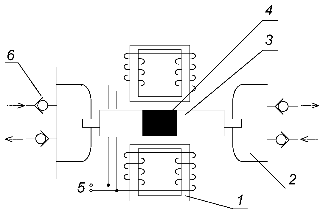
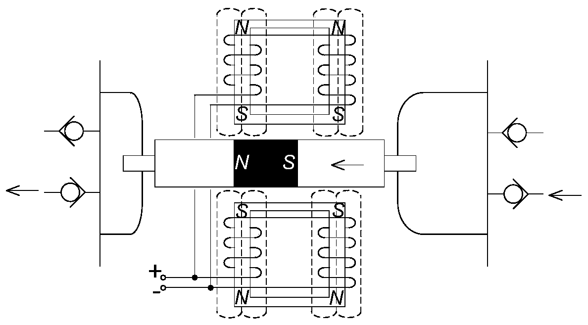
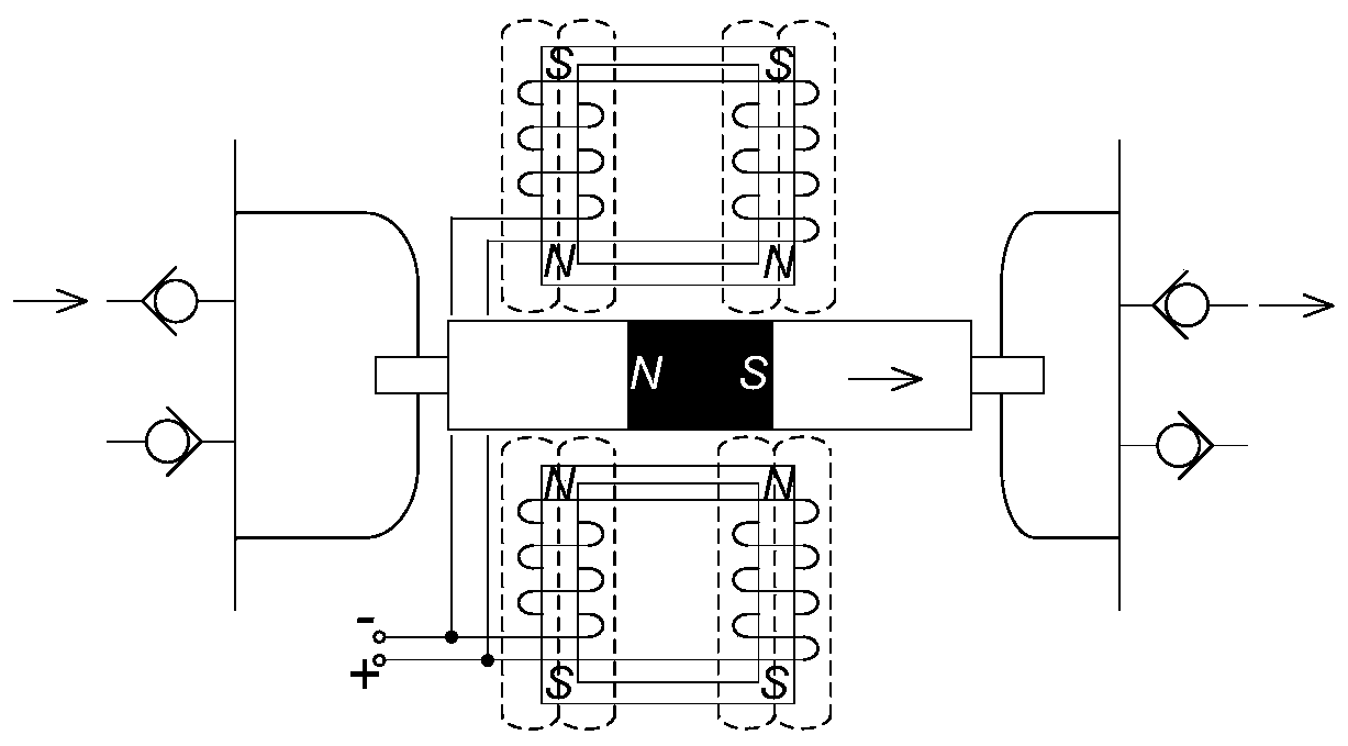
[0042] In the reciprocating air pump of the present invention, the moving device includes an electromagnetic coil and a magnet. The electromagnetic coil generates an alternating magnetic field when the alternating current is connected to drive the magnet to reciprocate axially, thereby realizing the air pump suction and exhaust circulation. In this embodiment, the structure of the motion device of the reciprocating air pump is as figure 1 Shown. The permanent magnet 4 is installed on the moving part 3 of the pump core, and two ends of the moving part are installed with cups 2. The armature coil 1 is arranged at a position parallel to the direction of movement of the moving part. The armature coil merges and leads two control wires 5 to the driving device. In addition, a check valve 6 is provided on each cup to prevent backflow of gas.
[0043] Such as figure 2 As shown, when the driving device energizes the armature coil in the forward direction, the S pole formed on the armat...
Embodiment 2
[0067] Compared with Embodiment 1, the reciprocating air pump of this embodiment also has a soft start function, and its control method also has a soft start step. The soft start process is as Picture 8 , First initialize the air pump movement frequency to 50Hz, cycle T to 20ms, and control signal power-on time t 0 Is 2ms. Due to the short energization time, the armature coil excitation time is short and the working current is small. Then every 300ms, the energization time increases by 1ms, the magnetization time of the armature coil becomes longer and longer, and the average working current gradually increases until the energization time reaches the preset value t 1 , The working current reaches the preset value. Where t 0 1 <10ms. In this way, by gradually increasing the power-on time of the drive device, the soft start process of the air pump from a small current to a large current is realized.
[0068] In the reciprocating air pump and its control method of the embodiment...
Embodiment 3
[0070] Compared with Embodiment 1 and Embodiment 2, the reciprocating air pump of this embodiment adopts a full-bridge drive circuit controlled by a single-chip microcomputer. The control program output by the single-chip microcomputer can be controlled by changing the power-on time t of the control signal. The magnitude of the reciprocating motion of the air pump movement device, so as to realize the air volume and pressure output of the air pump, and provide a variety of different air volume and pressure output combinations.
PUM
 Abstract
Description
Claims
Application Information
 - R&D
- Intellectual Property
- Life Sciences
- Materials
- Tech Scout
- Unparalleled Data Quality
- Higher Quality Content
- 60% Fewer Hallucinations
Browse by: Latest US Patents, China's latest patents, Technical Efficacy Thesaurus, Application Domain, Technology Topic, Popular Technical Reports.
© 2025 PatSnap. All rights reserved.Legal|Privacy policy|Modern Slavery Act Transparency Statement|Sitemap|About US| Contact US: help@patsnap.com


