An automatic pay-off car for electric cable wells

A cable well and automatic technology, which is applied in the direction of cable laying equipment, thin material handling, and conveying filamentous materials, etc., can solve the problems of unadjustable angle of wire laying, inability to adjust the angle of cable rack, and inability to lock cable rack

Active Publication Date: 2020-11-17
国网安徽省电力有限公司亳州供电公司
View PDF5 Cites 0 Cited by
  • Summary
  • Abstract
  • Description
  • Claims
  • Application Information

AI Technical Summary

Problems solved by technology

[0004] In order to solve the above problems, the present invention provides an automatic pay-off vehicle for electric cable wells, which can solve the problem that existing cable racks cannot adjust the angle of the cable racks and require different pay-offs for different types of cable wells. The rack and the pay-off rack will shake when paying off the wires, the cable rack cannot be locked in all directions, the cable rack needs to be carried manually, the angle of the wire cannot be adjusted, and the cable cannot be locked when the defense line is completed; Realize the function of all-round fixing of the cable pay-off rack and adjustable angle conduction of the cable. It can adjust the angle of the cable rack and can be used for different types of cable wells. Shaking, the cable rack can be locked in all directions, the cable rack can be manually pushed, the angle of the wire can be adjusted, and the cable can be locked when the defense line is completed, etc.

Method used


Image

  • An automatic pay-off car for electric cable wells
  • An automatic pay-off car for electric cable wells
  • An automatic pay-off car for electric cable wells

Examples


Embodiment Construction

[0031] In order to make the technical means, creative features, goals and effects achieved by the present invention easy to understand, the present invention will be further described below in conjunction with specific illustrations. It should be noted that, in the case of no conflict, the embodiments in the present application and the features in the embodiments can be combined with each other.

[0032] Such as Figure 8 As shown, the figure is a cross-sectional view of the cable well, the cable well is a circular structure, the upper end of the figure is the cable well cover, the middle part of the cable well is the cable well cover support, and the bottom is the cable well.

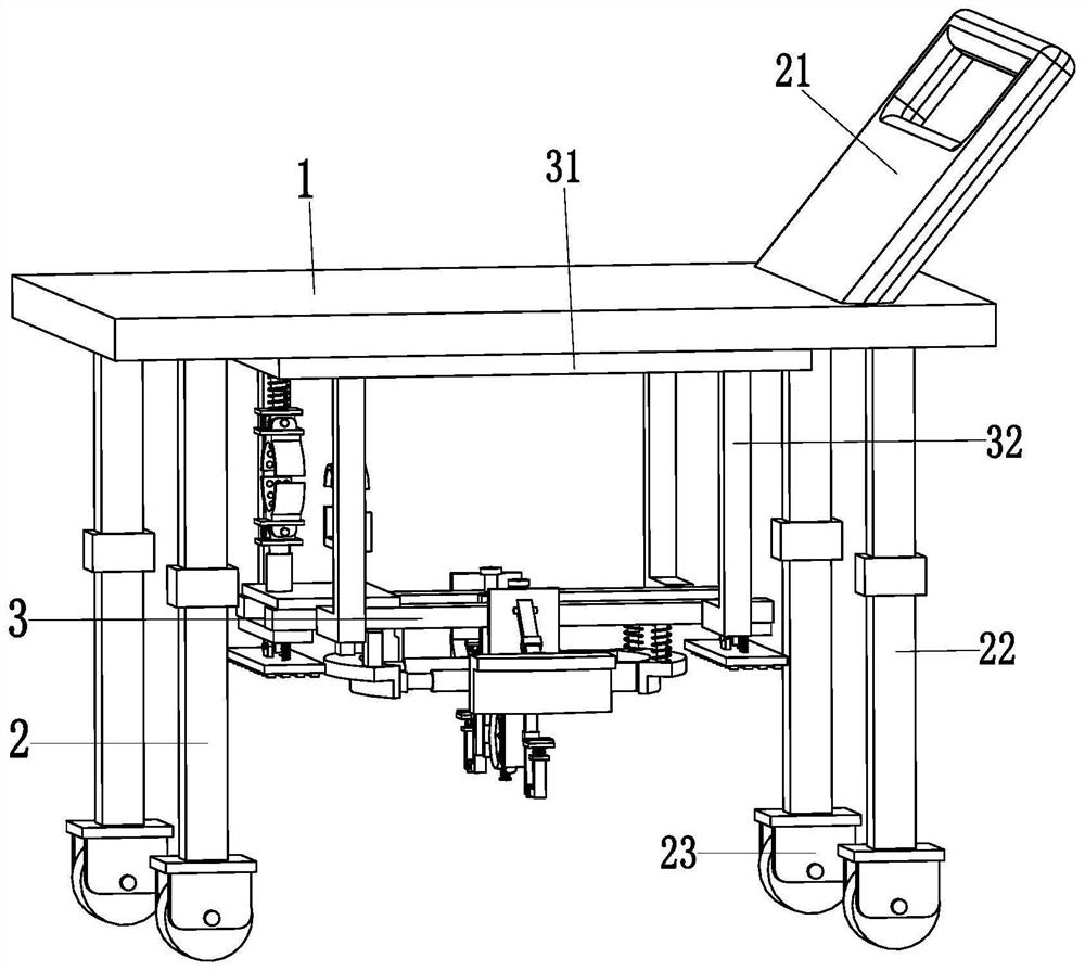
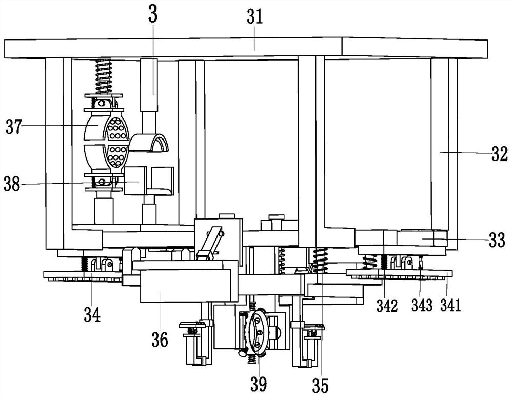
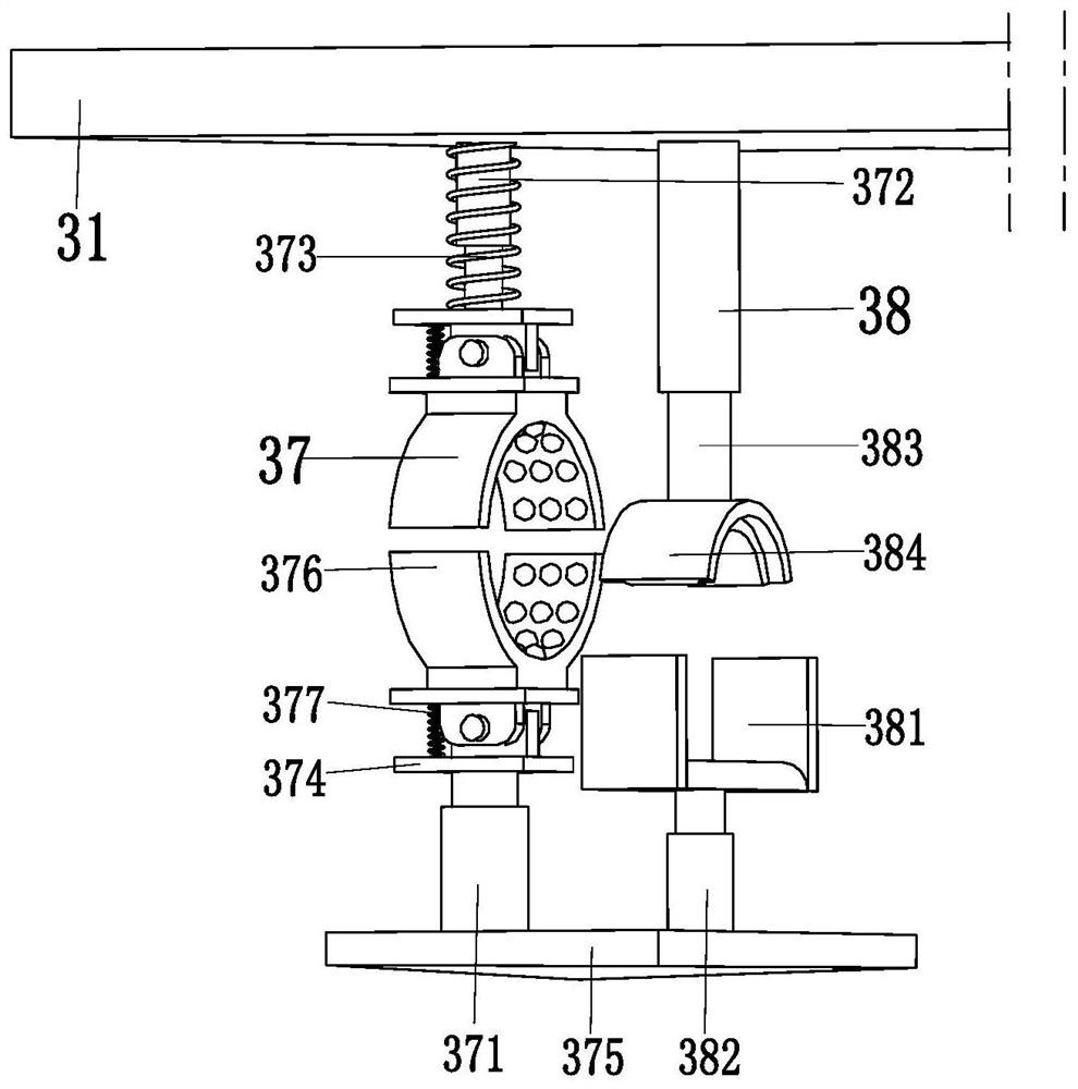
[0033] Such as Figure 1 to Figure 7 As shown, a kind of electric cable well automatic pay-off car, comprises mobile roof 1, mobile device 2 and pay-off device 3, described mobile roof 1 is equipped with mobile device 2, and pay-off device 3 is installed on the mobile roof 1 on the bottom.

[0034] D...


PUM


Abstract

The invention relates to an automatic paying-off construction trolley for a power cable well. The automatic paying-off construction trolley for the power cable well comprises a movable top plate, moving devices and a paying-off device. The moving devices are mounted on the movable top plate. The paying-off device is mounted at the bottom of the movable top plate and comprises a paying-off top plate, a paying-off connecting frame, a paying-off support, a supporting mechanism, a locking structure, a limiting structure, a paying-off mechanism, a speed reduction mechanism and a conveying mechanism. By adoption of the automatic paying-off construction trolley, the problems that when an existing cable stand is used for paying off a power cable, the angle of the cable stand cannot be adjusted, different paying-off frames are needed for cable wells of different types, the paying-off frames shake in the paying-off process, the cable stand cannot be comprehensively locked and needs to be manually transferred, the paying-off angle cannot be adjusted, and the cable cannot be locked after being paid off are solved; and a cable paying-off frame can be comprehensively fixed, and cables can be paid off in an angle-adjustable mode.

Description

technical field [0001] The invention relates to the technical field of electric power construction, in particular to an automatic pay-off vehicle for electric cable wells. Background technique [0002] For the beauty of the city, bid farewell to the era of utility poles on the road. Now a large number of cables are conducted through underground cable wells. With the increasing number of underground cable wells, the workload of cable release is also increasing, especially Large cables are especially heavy. [0003] Now the cable is usually laid out manually by placing a pulley or a simple pay-off frame outside the cable well, which will cause the cable to be scratched by the cable well or the cable will damage the cable well, the edge of the well cover and the waterproof layer. Such as Figure 8 As shown, the cable well is a circular structure, the upper end of the figure is the cable well cover, the middle part of the cable well is the cable well cover support, and the bott...

Claims


Application Information

Patent Timeline
Patent Type & Authority Patents(China)
IPC IPC(8): B65H49/32H02G1/06
CPCB65H49/324B65H2701/34H02G1/06
Inventor 戴明明李强王康马婧
Owner 国网安徽省电力有限公司亳州供电公司
Why Eureka
Try Eureka