A satellite antenna for communication transmission

A satellite antenna and antenna technology, applied in the field of communication transmission, can solve the problems that the antenna rotation angle cannot be adjusted accurately, the reflector of the antenna cannot be supported, and the antenna fixing effect is poor, so as to achieve increased support and fixing effect, good fixing effect, good dynamic performance

Active Publication Date: 2020-07-17
铭宸(唐山)航天电子装备科技有限公司
View PDF10 Cites 0 Cited by
  • Summary
  • Abstract
  • Description
  • Claims
  • Application Information

AI Technical Summary

Problems solved by technology

[0003] In order to solve the above-mentioned problems, the present invention provides a satellite antenna for communication transmission, which can solve the problems that existing antennas cannot be stably fixed to different types of antennas, the fixing effect of the antenna is poor, and the antenna will be damaged under special weather conditions. Shaking occurs, the rotation of the antenna needs manual adjustment, the rotation angle of the antenna cannot be adjusted accurately manually, and the reflector of the antenna cannot be supported; it can realize the clamping and fixing of the antenna and the adjustment of the angle, and the antenna after the angle adjustment The function of stable support of the reflector can stably fix different types of antennas, the fixing effect of the antenna is good, the antenna will not shake under special weather conditions, the rotation of the antenna can be automatically adjusted, and the rotation of the antenna can be adjusted precisely by mechanization Angle, the reflector of the antenna can be supported, etc.

Method used


Image

  • A satellite antenna for communication transmission
  • A satellite antenna for communication transmission
  • A satellite antenna for communication transmission

Examples


Embodiment Construction

[0025] In order to make the technical means, creative features, goals and effects achieved by the present invention easy to understand, the present invention will be further described below in conjunction with specific illustrations. It should be noted that, in the case of no conflict, the embodiments in the present application and the features in the embodiments can be combined with each other.

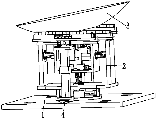
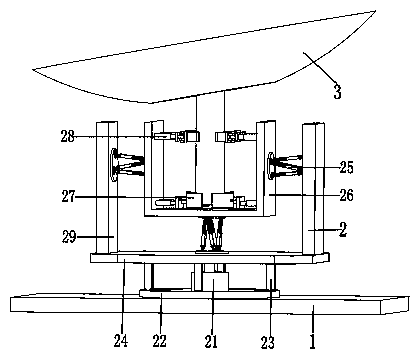
[0026] Such as Figure 1 to Figure 7 As shown, a satellite antenna for communication transmission includes a mounting base plate 1, a rotating device 2, an antenna 3 and a supporting device 4. The mounting base plate 1 is provided with mounting holes, and the present invention can pass through the mounting holes on the mounting base plate 1 The present invention is installed on the cement platform with expansion screws, a rotating device 2 is installed on the upper end surface of the middle part of the installation base plate 1, the antenna 3 is located in the rotation device 2, and ...


PUM


Abstract

The invention relates to a satellite antenna for communication transmission. The antenna includes mounting base plate, rotating device, Antenna and support device, The mounting bottom plate is provided with mounting holes. The invention can be mounted on a cement platform by using expansion screws through the mounting holes on the mounting bottom plate. A rotating device is mounted on the upper end surface of the middle part of the mounting bottom plate. The antenna is positioned in the rotating device and a supporting device is mounted on the front and rear ends of the middle part of the mounting bottom plate. The rotating device comprises a rotating motor, a rotating chute, a rotating slide rod, a rotating plate, a parallel mechanism, a support inner frame, a locking mechanism, a clamping mechanism and a rotating side plate. The invention can solve the problems that different types of antennas cannot be stably fixed when the existing antennas are fixed, the fixing effect of the antennas is poor, the antennas can be shaken under special weather conditions, the rotation angle of the antennas cannot be accurately adjusted by manpower, the reflectors of the antennas cannot be supported, and the like.

Description

technical field [0001] The invention relates to the technical field of communication transmission, in particular to a satellite antenna for communication transmission. Background technique [0002] The satellite antenna is a metal paraboloid, which is responsible for reflecting the satellite signal to the feed source and high frequency head at the focal point, which is a kind of communication transmission; the satellite antenna is generally connected to a cylinder, and then the cylinder is fixed and installed Then install the mounting frame on the cement platform with expansion screws. After fixing it, adjust the angle of the antenna so that the antenna can receive signals normally. The existing problems of the mounting frame are as follows. Different types of antennas need to use different The fixing frame is used for connection and fixing. The antenna connecting frame is suitable for a single antenna, and the fixing effect of the mounting frame on the antenna is poor. Espe...

Claims


Application Information

Patent Timeline
Patent Type & Authority Patents(China)
IPC IPC(8): H01Q1/12H01Q3/08H01Q1/28
CPCH01Q1/12H01Q1/28H01Q3/08
Inventor 林瑞
Owner 铭宸(唐山)航天电子装备科技有限公司
Why Eureka
Try Eureka