
Method and device of full-domain cutting force modeling in rotary ultrasonic vibration milling

An ultrasonic vibration and rotary ultrasonic technology, applied in the field of ultrasonic vibration machining, can solve the problems of complex rotary ultrasonic vibration machining process, numerous process parameters, and the inability to predict the machining process by the empirical model of cutting force.

Active Publication Date: 2018-11-02
BEIHANG UNIV
View PDF6 Cites 9 Cited by
  • Summary
  • Abstract
  • Description
  • Claims
  • Application Information

AI Technical Summary

Problems solved by technology

[0005] However, due to the complexity of the rotary ultrasonic vibration machining process and the large number of process parameters involved, the cutting force empirical model cannot effectively predict the machining process under different process conditions.
However, the theoretical analysis modeling method is only based on a single material removal mechanism for cutting force modeling, which cannot fully reflect the cutting characteristics of hard and brittle materials ultrasonic vibration machining, so it is difficult to guide the cutting force control and process optimization in actual machining

Method used


Image

  • Method and device of full-domain cutting force modeling in rotary ultrasonic vibration milling
  • Method and device of full-domain cutting force modeling in rotary ultrasonic vibration milling
  • Method and device of full-domain cutting force modeling in rotary ultrasonic vibration milling

Examples


Embodiment Construction

[0020] In order to make the purpose, technical solutions and advantages of the present invention clearer, the technical solutions in the present invention will be clearly and completely described below in conjunction with the accompanying drawings in the embodiments of the present invention. Obviously, the described embodiments are the embodiment of the present invention. Some, but not all, embodiments. Based on the embodiments of the present invention, all other embodiments obtained by persons of ordinary skill in the art without making creative efforts belong to the protection scope of the present invention.

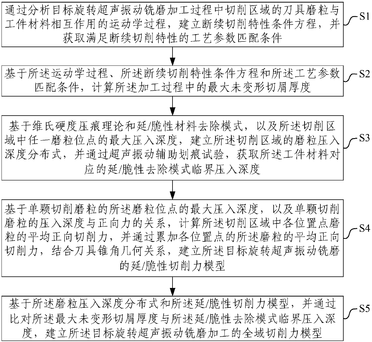
[0021] As an aspect of the embodiment of the present invention, this embodiment provides a global cutting force modeling method for rotary ultrasonic vibration milling, refer to figure 1 , is a flow chart of a global cutting force modeling method for rotary ultrasonic vibration milling in an embodiment of the present invention, including:

[0022] S1. By analyzing the...


PUM


Abstract

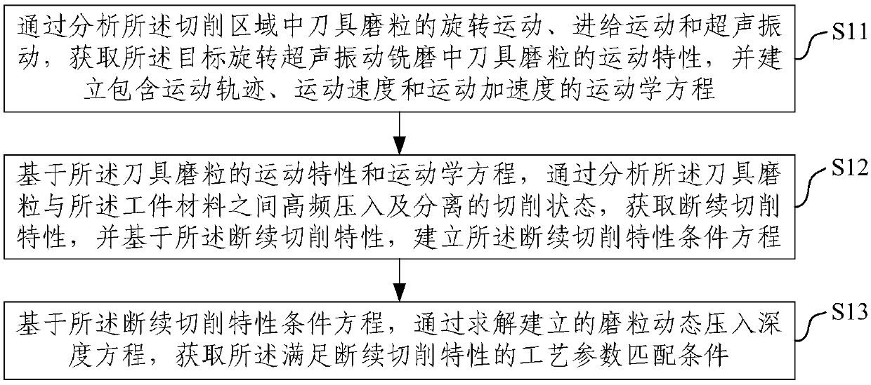
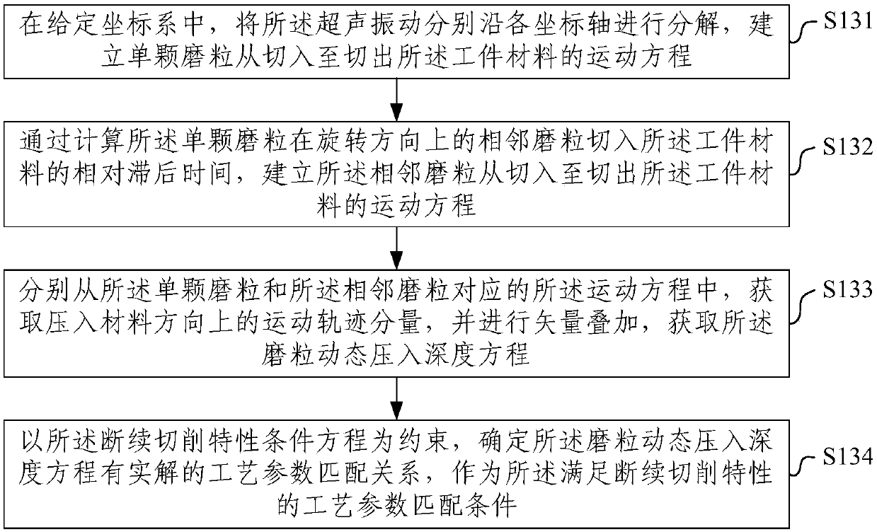
The invention provides a method and a device of full-domain cutting force model in rotary ultrasonic vibration milling. By carrying out the kinematics analysis between a tool abrasive grain and a workpiece material interaction in the machining process, a technology parameter matching relation meeting the vibration separation of a cutting area is obtained, and a condition equation of an intermittent cutting characteristic is established; and according to an ultrasonic vibration auxiliary scratch test, critical press-in depth of ductility or brittleness removal mode changing of a material is obtained, the abrasive particle press-in depth distribution relation of the cutting area is established, the abrasive grain loads of different positions of the cutting area are accumulated, and ductilityor brittleness cutting force model is obtained correspondingly, the models are fused according to the critical press-in depth and the maximum cutting thickness, and the rotary ultrasonic vibration machining whole-domain cutting force model is obtained. According to the device, the rotary ultrasonic vibration machining characteristic and a removing mechanism can be more comprehensively reflected,so that the cutting force prediction and the technology optimization of the actual machining can be effectively guided.

Description

technical field [0001] The present invention relates to the technical field of ultrasonic vibration machining, and more specifically, to a method and device for modeling global cutting force of rotary ultrasonic vibration milling and grinding. Background technique [0002] With the continuous improvement of equipment service performance requirements in the industrial field, advanced materials such as composite materials and ultra-high temperature ceramics have been widely used. At the same time, due to the high strength and high hardness of this kind of material, the processing process is prone to many problems such as large cutting force and serious processing damage. Traditional cutting processing technology is difficult to meet its manufacturing needs. [0003] Rotary ultrasonic vibration milling is an effective technical approach to realize high-efficiency and low-damage processing of high-performance materials, but the research on this technology is still insufficient. ...

Claims


Application Information

Patent Timeline
IPC IPC(8): B24B1/04
CPCB24B1/04
Inventor 袁松梅李真李麒麟
Owner BEIHANG UNIV
Learn More