Lamp capable of adjusting light spots in orienteering manner and light spot adjusting method

An adjustment method and light spot technology, which is applied in the direction of light source fixing, lighting device parts, lighting devices, etc., can solve the problem of changing the position of the light spot, etc., and achieve the effect of ingenious principle, simple structure, cost saving and cycle time

Pending Publication Date: 2018-10-30
WAC LIGHTING DONGGUAN +1
View PDF7 Cites 2 Cited by
  • Summary
  • Abstract
  • Description
  • Claims
  • Application Information

AI Technical Summary

Problems solved by technology

[0003] In fact, not only for recessed lights, many lamps are affected by some installation environments. The lamp body is generally fixed and installed, and the position of the light spot cannot be changed by changing the position of the light source. At this time, a new adjustment method is needed to achieve the change. The purpose of spot position

Method used


Image

  • Lamp capable of adjusting light spots in orienteering manner and light spot adjusting method
  • Lamp capable of adjusting light spots in orienteering manner and light spot adjusting method
  • Lamp capable of adjusting light spots in orienteering manner and light spot adjusting method

Examples


Embodiment Construction

[0027] The technical solutions of the present invention will be further described below in conjunction with the accompanying drawings and through specific implementation methods.

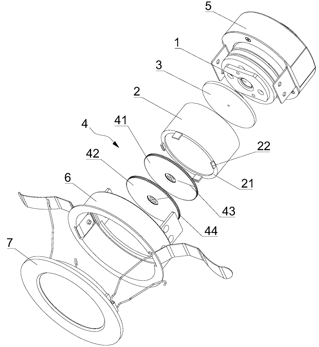
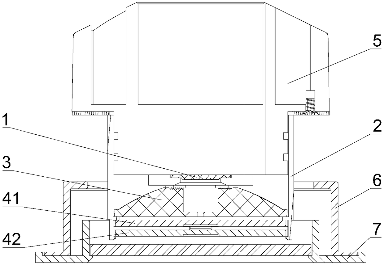
[0028] see figure 1 and 2 As shown, this embodiment provides a luminaire with directional adjustable spot, which mainly includes a lamp body. The lamp body includes a light source 1, an optical element and a fixed cylinder 2. A radiator 5 is arranged behind the light source 1, and the fixed cylinder 2 is fixed on a The housing of the radiator 5 and the light source 1 is sheathed therein, the outer cover of the fixed cylinder 2 is provided with an outer frame 6, the outer frame 6 is connected with the housing of the radiator 5, and the mouth of the outer frame 6 corresponding to the fixed cylinder 2 is provided with an opening that can be opened. The combined panel 7, the fixed cylinder 2 is set facing the light source 1, the optical elements include a lens 3, a first polarizer 41 and a second polar...


PUM


Abstract

The invention discloses a lamp capable of adjusting light spots in an orienteering manner. The lamp comprises a lamp body comprising a light source, an optical element and a fixing barrel, the fixingbarrel right faces the light source, the optical element comprises a lens, a first polarizer and a second polarizer, the first polarizer and the second polarizer are each of a micro-lens array structure, a limiting part is arranged at the end, far away from the light source, on the fixing barrel, the lens is arranged in the fixing barrel and is limited by the limiting part, two pairs of snap joints different in heights are arranged on the outer side of the limiting part, the first polarizer and the second polarizer can be rotationally embedded into the two pairs of snap joints, and the lens, the first polarizer and the second polarizer are sequentially arranged in front of the light source. A light spot adjusting method is disclosed. By means of the lamp capable of adjusting light spots inthe orienteering manner and the light spot adjusting method, the two polarizers are rotated to change the optical ray refraction angel so as to change the light emitting projection angle, free deflection of the projection optical spots with a certain lighting scope is achieved, and orienteering lighting is carried out.

Description

technical field [0001] The invention relates to a lamp, in particular to a lamp capable of adjusting the position of a light spot and a method for adjusting the light spot. Background technique [0002] Recessed lamps, as a kind of lamps embedded in walls or panels, generally have a fixed light projection angle. To achieve directional lighting, a special angle adjustment structure is generally required. As far as current downlights are concerned, the angle adjustment structure is generally It is more complicated, has more parts, and the cost of lamps is also higher. In addition, if the adjustment operation is performed frequently, it is easy to cause the angle adjustment mechanism to fail or cause mechanical failure, which will affect the service life of the lamp. Compared with some exposed spotlights, recessed lights are not as flexible as them. If an additional adjustment structure is added, firstly, the requirements for the embedded space will be increased, and secondly,...

Claims


Application Information

Patent Timeline
Patent Type & Authority Applications(China)
IPC IPC(8): F21V14/06
CPCF21V14/06
Inventor 胡建秋李仁云甘明
Owner WAC LIGHTING DONGGUAN
Why Eureka
Try Eureka