
Wireless charging device of capacitance compensation network based on variable topology structure

A topology and capacitance compensation technology, applied in battery circuit devices, circuit devices, current collectors, etc., can solve the problem that the reactance cannot be cancelled, the circuit capacitance value cannot be changed in time, and the resonant frequency of the transmitting coil and the receiving coil is prone to deviation, etc. It can solve the problem of fixed capacitor topology, keep energy to maximize transmission, and be beneficial to integration.

Inactive Publication Date: 2018-10-26
TIANJIN UNIV
View PDF2 Cites 2 Cited by
  • Summary
  • Abstract
  • Description
  • Claims
  • Application Information

AI Technical Summary

Problems solved by technology

[0004] In practical applications, due to component tolerances, distance changes, and operating frequency changes, the resonant frequencies at the transmitting coil and receiving coil are prone to deviations
Due to the fixed structure of the existing capacitor array, it is impossible to change the capacitance value in the circuit in time, and the capacitance matching value is unique. It cannot completely match the inductance coil under the new charging frequency, the reactance in the circuit cannot be offset, and the resonance state of the device circuit occurs. change, transfer energy in a non-resonant state, resulting in energy loss

Method used


Image

  • Wireless charging device of capacitance compensation network based on variable topology structure
  • Wireless charging device of capacitance compensation network based on variable topology structure
  • Wireless charging device of capacitance compensation network based on variable topology structure

Examples


Embodiment Construction

[0056] Below in conjunction with accompanying drawing and specific embodiment the present invention is described in further detail:

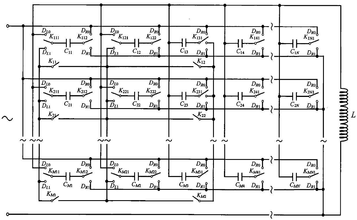
[0057] figure 1 is the capacitive compensation network of the present invention M x N Schematic diagram of capacitor matrix; figure 1 As shown, a wireless charging device based on a capacitance compensation network with a variable topology structure includes a charging power supply, a transmitting coil set on the transmitting side of the source side, a receiving coil set on the receiving side of the secondary side, a charging load, and a variable The topology capacitor matrix and the control capacitor matrix change the relay group of the topology structure. The capacitor matrix is ​​connected in series and in parallel with the transmitting coil through the control of the relay group to form an equivalent parallel resonant circuit on the transmitting side. The receiving coil receives wireless signals from the transmitting coil. The transmitted...


PUM


Abstract

The invention discloses a wireless charging device of a capacitance compensation network based on a variable topology structure. The wireless charging device comprises a charging power supply, an emission coil arranged on an emission side, a receiving coil arranged on a receiving side, a charging load, a capacitance matrix with a variable topology structure and a relay group for controlling the capacitance matrix to change the topology structure. The capacitance matrix is serially and paralelly connected with the emission coil through control of the relay group, so an equivalent source edge emission coil side parallel resonance circuit is formed. An auxiliary side receiving coil side emission coil receives wireless transmitted energy and charges the load. The charging power supply provideselectric power for the parallel connection resonance circuit of the emission coil side. By use of the capacitance matrix with the variable topology structure, the topology structure of the capacitance matrix is dynamically adjusted through limited number of capacitors, so the capacitance value range of the compensation capacitors is remarkably increased, the device is enabled to carry out wireless transmission of the energy by keeping the resonance state under more different charging frequencies and maximum transmission of the energy is kept.

Description

technical field [0001] The invention relates to a wireless charging device, in particular to a wireless charging device based on a variable topology capacitance compensation network. Background technique [0002] With the popularity of portable electronic devices, the continuous development of power electronics technology and the continuous improvement of the topological performance of transmission coils, wireless energy transmission technology has become mature. [0003] Magnetic resonance coupled wireless energy transmission, as a transmission method with high energy transmission efficiency and long transmission distance, uses several electromagnetic devices with the same resonant frequency to cooperate with inductive coils working at a specific frequency to couple each other to generate electromagnetic energy. Resonance, and finally transfer the energy to the load. In the magnetic resonance coupling wireless energy transmission device, the primary and secondary transmiss...

Claims


Application Information

Patent Timeline
Patent Type & Authority Applications(China)
IPC IPC(8): H02J50/12H02J7/02
CPCH02J7/025H02J50/12
Inventor 张镇艾文杰邓斌魏熙乐于海涛刘晨伊国胜王江
Owner TIANJIN UNIV
Learn More