Laying method convenient for position exchange of cable line in electric power cabin

A technology of cable line and position exchange, applied in the direction of cable laying equipment, etc., can solve the problems of irregular laying method and endanger the safe operation of cable line, etc., and achieve the effect of saving project cost, simple construction process and tight clamping.

Inactive Publication Date: 2018-10-26
STATE GRID CORP OF CHINA +1
View PDF11 Cites 0 Cited by
  • Summary
  • Abstract
  • Description
  • Claims
  • Application Information

AI Technical Summary

Problems solved by technology

[0005] In view of this, the object of the present invention is to address the deficiencies of the prior art and provide a laying method that facilitates the exchange of positions of the cable lines in the power cabin, so as to solve the problem of the non-standard laying method that used the maintenance channel to bypass the laying of the outgoing lines in the past and endanger the safety of the cable lines. For the problem of operation, the method for the spiral rolling transposition of the cable line in the power cabin of the present invention does not need to increase the width and height of the power cabin, and only needs to adjust the amplitude of the spiral according to the needs of meeting the minimum bending radius of the cable, and can pass through multiple For the first time, helical laying is adopted, and the positions are rolled in turn to realize the transposition between multiple circuits, so that any circuit in the power cabin can go out from the top (or bottom) outlet

Method used


Image

  • Laying method convenient for position exchange of cable line in electric power cabin
  • Laying method convenient for position exchange of cable line in electric power cabin
  • Laying method convenient for position exchange of cable line in electric power cabin

Examples


Embodiment 1

[0027] The invention discloses a laying method for conveniently changing the position of the cable line in the electric cabin, comprising the following steps,

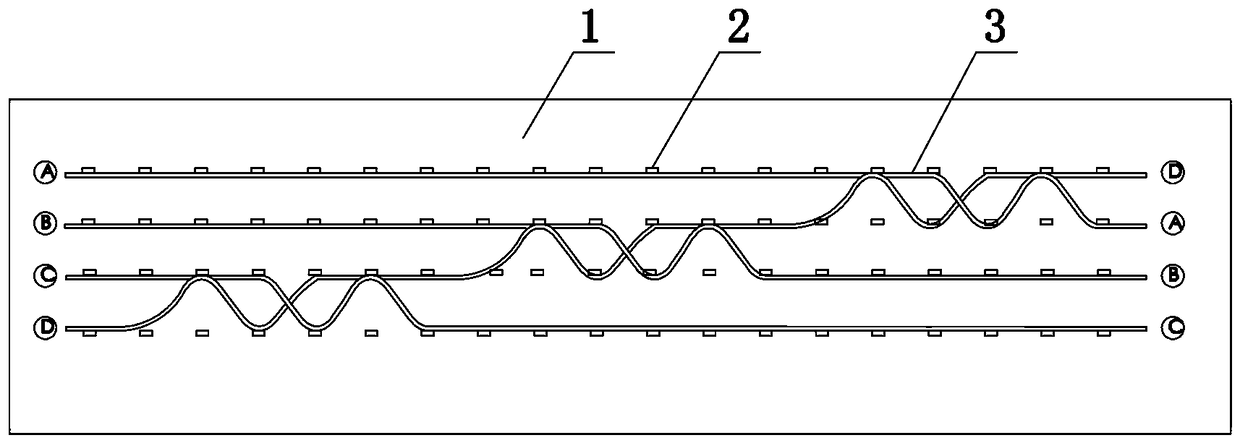
[0028] Step 1) Install the cable support frame 2 in the power cabin 1, and the support frame 2 is set in multiple rows and columns;

[0029] Step 2) Lay multiple cables 3 (four shown in the figure) in a spiral manner and fix them on the support frame 2. The spiral directions of two adjacent cables 3 are the same, and the positions of the spirals are misplaced (such as figure 1 shown).

[0030] figure 1 Taking the four cables arranged vertically as an example, the purpose is to realize the right top outlet of the bottom circuit (the right end of the D-number cable at the bottom of the power cabin is routed from the top of the power cabin), and the method of three times of spiral transposition from left to right is adopted: The first time is to transpose the screw of D cable and C cable (a single cable can be turned up...

Embodiment 2

[0032] The invention discloses a laying method for conveniently changing the position of the cable line in the electric cabin, comprising the following steps,

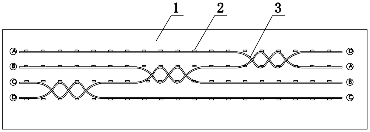
[0033] Step 1) Install the cable support frame 2 in the power cabin 1, and the support frame 2 is set in multiple rows and columns;

[0034] Step 2) Lay several cables 3 (four shown in the figure) in a spiral manner and fix them on the support frame 2. The spiral sections of multiple cables 3 do not touch each other, and the spiral direction of two adjacent cables 3 on the contrary.

[0035] figure 2 Take the four cables arranged vertically as an example. The purpose is to realize the right top outlet of the bottom circuit (the right end of the D-number cable at the bottom of the power cabin is routed from the top of the power cabin), and the method of three-time spiral transposition from left to right is adopted. : The first time is to transpose the screw of D cable and C cable (a single cable can be turned up by s...

Embodiment 3

[0038] The present invention is a kind of laying method that is convenient for changing the position of the cable line in the electric cabin, comprising the following steps,

[0039] Step 1) Install the cable support frame 2 in the power cabin 1, and the support frame 2 is set in multiple rows and columns;

[0040] Step 2) Lay several cables 3 (four shown in the figure) in a spiral manner and fix them on the support frame 2. The spiral sections of multiple cables 3 do not touch each other, and the spiral direction of two adjacent cables 3 on the contrary.

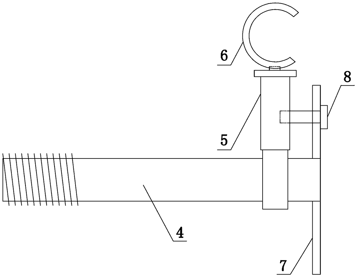
[0041] like Figure 4 As shown, the support frame 2 includes a support rod 4, one end of the support rod 4 is provided with an external thread, and is fixed on the bulkhead of the power cabin 1 by an expansion screw, and the other end of the support rod 4 is provided with a support mechanism, and the support mechanism is designed to be two up and down. The supporting mechanism includes a connecting rod 5 and a C-shaped ho...


PUM


Abstract

The invention belongs to the technical field of power cable engineering, and particularly relates to a laying method convenient for position exchange of a cable line in an electric power cabin. The method comprises the following steps that step 1) multiple rows and columns of supporting frames of cables are installed in the electric power cabin; and step 2) the cables are fixed on the supporting frames in a spiral laying mode, and spiral sections of the cables do not make contact with each other. According to the method, extra increase of the width and the height of the power cabin is not needed, the spiral amplitude is adjusted by only meeting the requirement for the minimum bending radius of the cable, and through the spiral laying for multiple times, the rolling position exchange is carried out orderly, the position change between a plurality of loops is realized, and an outgoing line from a top (or bottom) outlet of any loop in the power cabin can be met. The construction cost is controlled while the occupation of a maintenance corridor and the damage to a cable insulation layer are avoided.

Description

technical field [0001] The invention belongs to the technical field of power cable engineering, in particular to a laying method for conveniently changing positions of cable lines in a power cabin. Background technique [0002] Since the power compartment of the underground comprehensive utility gallery is an integral part of the entire comprehensive utility gallery, the height and width of the utility gallery are restricted to those of other cabins adjacent to it, which makes the construction form, cross-sectional scale, and scheme of incoming and outgoing lines of the electric cabin different from those of the other cabins. Conventional cable trenches or cable tunnels. Especially the form of cable entry and exit, due to the obstruction of adjacent cabins, the entry and exit lines of the power cabin generally use the top or bottom exit lines, and then cross (drill through) other cabins to the left and right sides to the two sides of the integrated pipe gallery. side laying...

Claims


Application Information

Patent Timeline
Patent Type & Authority Applications(China)
IPC IPC(8): H02G1/06
Inventor 齐道坤刘湘莅郭新菊梁晟路晓军唐旻景川刘存凯吴迪
Owner STATE GRID CORP OF CHINA
Why Eureka
Try Eureka