
Phase-change hot pipe and liquid circulated cooling composite cooling device

A technology of liquid circulation and heat dissipation device, applied in the direction of transformer/inductor cooling, etc., can solve problems such as system outage, and achieve the effect of reducing volume, enhancing cooling effect, and increasing operating load

Pending Publication Date: 2018-10-26
辽宁和天精工科技有限公司
View PDF1 Cites 1 Cited by
  • Summary
  • Abstract
  • Description
  • Claims
  • Application Information

AI Technical Summary

Problems solved by technology

Especially for liquid circulation cooling and heat dissipation schemes, such as forced water cooling circulation, self-circulation oil cooling or forced circulation oil cooling system, etc. are set up in an independent working mode. When the liquid circulation cooling system fails or is out of operation based on special requirements, The corresponding system is bound to be forced to shut down, causing a lot of inconvenience

Method used


Image

  • Phase-change hot pipe and liquid circulated cooling composite cooling device
  • Phase-change hot pipe and liquid circulated cooling composite cooling device
  • Phase-change hot pipe and liquid circulated cooling composite cooling device

Examples


Embodiment 1

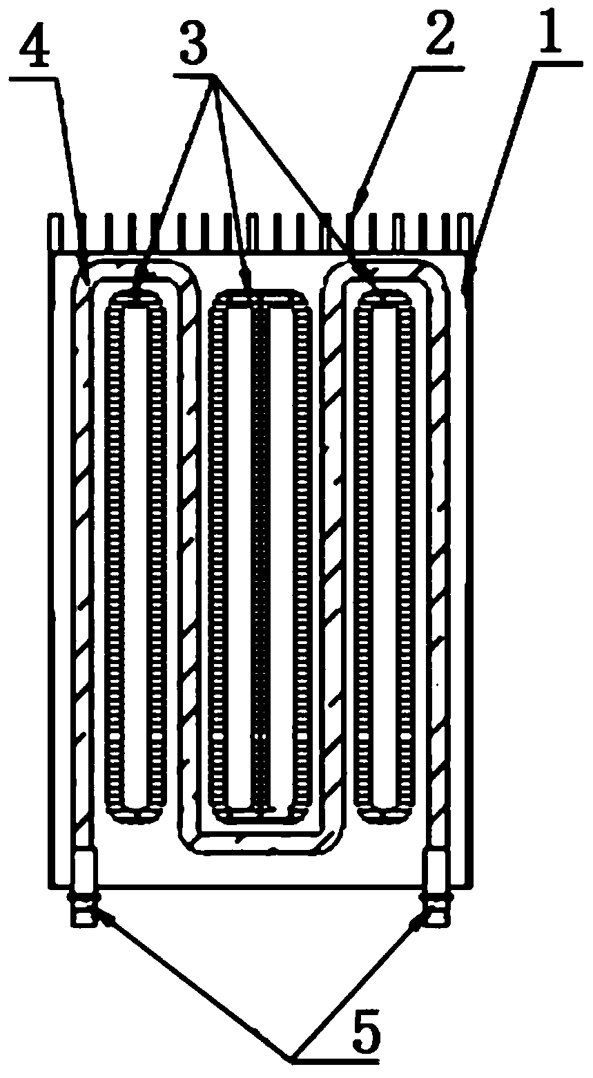
[0033] See figure 1 , figure 2 , phase change heat pipe 3 and liquid circulation cooling composite cooling device, including liquid circulation cooling system, phase change heat pipe 3 cooling system, the two systems are arranged alternately, the liquid circulation cooling system is composed of liquid cooling circulation loop 4, phase change heat pipe 3 The heat dissipation system is a phase change heat pipe 3; the liquid cooling circulation loop 4 is arranged in a serpentine shape, and several phase change heat pipes 3 are arranged between the liquid cooling circulation loop 4 and are close to the liquid cooling circulation loop 4. The phase change heat pipe 3 is annular or The sun-shaped structure, the liquid cooling circulation loop 4 and the phase change heat pipe 3 are arranged in the same plane, and the two ends of the liquid cooling circulation loop 4 are provided with a cooling liquid inlet and outlet 5 . The liquid cooling circulation circuit 4 and the phase change ...

Embodiment 2

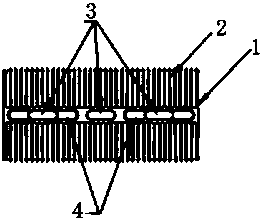
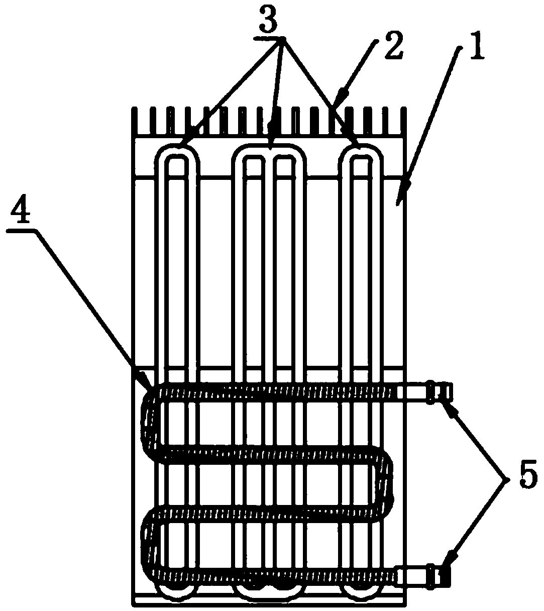
[0037] See image 3 , Figure 5 , the phase change heat pipe 3 and the liquid circulation cooling compound heat dissipation device, including the liquid circulation cooling system and the phase change heat pipe 3 heat dissipation system, the two systems are stacked and arranged in a composite manner, and the liquid circulation cooling system is composed of the liquid cooling circulation loop 4. The heat dissipation system of the heat pipe 3 is composed of several phase change heat pipes 3; the liquid cooling circulation loop 4 is arranged in a serpentine shape and fixed on the body 1; several phase change heat pipes 3 are arranged side by side in the body 1; The cooling circulation circuits 4 are stacked and installed, and the liquid cooling circulation circuits 4 are arranged on both sides of the body 1 . The liquid cooling circuit 4 can be arranged vertically, see image 3 ; The liquid cooling circuit 4 can also be arranged horizontally, see Figure 4 . Both ends of the ...

Embodiment 3

[0039] See Image 6 , Figure 7 , phase change heat pipe 3 and liquid circulation cooling composite cooling device, including liquid circulation cooling system, phase change heat pipe 3 cooling system, the two systems are nested together, the liquid circulation cooling system is liquid cooling circulation loop 4, phase change heat pipe 3 The heat dissipation system is a phase-change heat pipe 3; the cross section of the liquid cooling circulation loop 4 is ring-shaped, and the phase-change heat pipe is nested in the liquid cooling circulation loop 4, and the cooling liquid is passed through the ring structure, and the liquid cooling circulation loop 4 is fixed inside the body 1, and the body 1 Radiating fins 2 are fixed on the outside; a phase-changing heat pipe is arranged at the center of the liquid cooling circulation loop 4 . A capillary liquid-absorbing wick may also be arranged in the evaporation chamber of the phase-change heat pipe 3 .

[0040] In the above-mentioned...


PUM


Abstract

The invention relates to a phase-change hot pipe and liquid circulated cooling composite cooling device. The phase-change hot pipe and liquid circulated cooling composite cooling device comprises a liquid circulated cooling system and a phase-change hot pipe cooling system, wherein the liquid circulated cooling system comprises a forced water-cooling circulation, automatic circulation oil-coolingor forced circulation oil-cooling system, the phase-change hot pipe cooling system is a phase-change hot pipe, the liquid circulated cooling system and the phase-change hot pipe cooling system are simultaneously and integrally arranged, cooling fins are arranged on surfaces of the liquid circulated cooling system and the phase-change hot pipe cooling system, the phase-change hot pipe cooling system is heated to generate phase change so as to dissipate hot of a hot source out, and meanwhile, heat of the liquid circulated cooling system is fully absorbed and is dissipated. The phase-change hot pipe and liquid circulated cooling composite cooling device has the advantages that the phase-change hot pipe and liquid circulated cooling composite cooling device is used for controlling temperaturerising of an ultra-large capacity oil-immersed transformer, the oil temperature cooling capability is powerfully improved, the size of the transformer oil-cooling system is greatly reduced, meanwhile,the cooling effect of a transformer winding is improved, and the phase-change hot pipe and liquid circulated cooling composite cooling device has positive significance in prolonging insulation thermal aging lifetime of the transformer and improving the running load of the transformer.

Description

technical field [0001] The invention relates to a phase-change heat pipe and liquid circulation cooling compound heat dissipation device. Background technique [0002] In the current heat transfer and heat dissipation applications, liquid circulation cooling and heat dissipation by phase change heat pipes are designed for independent use. Especially for liquid circulation cooling and heat dissipation schemes, such as forced water cooling circulation, self-circulation oil cooling or forced circulation oil cooling system, etc. are set up in an independent working mode. When the liquid circulation cooling system fails or is out of operation based on special requirements, The corresponding system is bound to be forced to shut down, causing a lot of inconvenience. Contents of the invention [0003] In order to overcome the deficiencies in the prior art, the object of the present invention is to provide a composite heat sink with phase change heat pipe and liquid circulation co...

Claims


Application Information

Patent Timeline
IPC IPC(8): H01F27/08H01F27/10H01F27/12H01F27/16H01F27/18H01F27/22
CPCH01F27/08H01F27/10H01F27/12H01F27/16H01F27/18H01F27/22
Inventor 张馨元邱明惠
Owner 辽宁和天精工科技有限公司
Learn More