Flight indicating device, system and related method

A technology for equipment and propulsion equipment, which is applied in the direction of aircraft, unmanned aerial vehicles, remote control aircraft, etc., and can solve the problem that users cannot clearly see the indicator lights.

Active Publication Date: 2022-02-08
SZ DJI TECH CO LTD
View PDF6 Cites 0 Cited by
  • Summary
  • Abstract
  • Description
  • Claims
  • Application Information

AI Technical Summary

Problems solved by technology

When the UAV 100 is flying very high above the user, the user may not be able to clearly see the traditional indicator lights 105

Method used


Image

  • Flight indicating device, system and related method
  • Flight indicating device, system and related method
  • Flight indicating device, system and related method

Examples


Embodiment Construction

[0016] 1. Overview

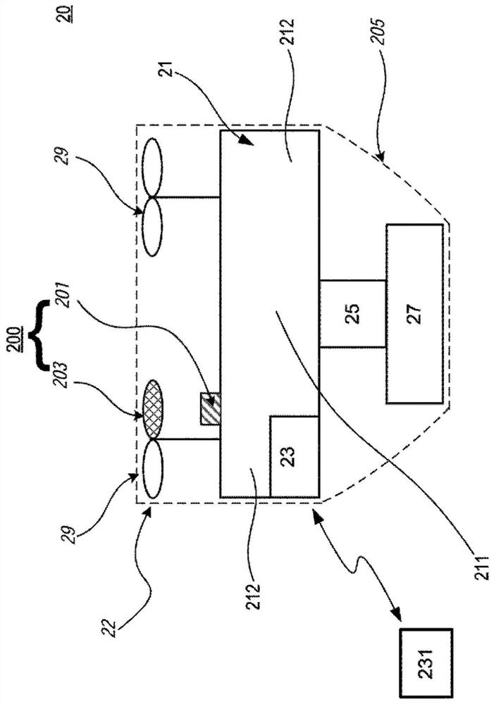
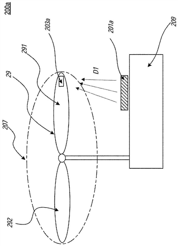
[0017] The present technology generally relates to devices, systems, and methods for indicating the state of a UAV or the state of a control terminal (eg, a remote control for a UAV, or a base for a UAV). Representative equipment may include propulsion equipment. Examples of propulsion devices include propellers, blades, paddles, rotatable members that move air / liquid in their vicinity, and / or other suitable devices. The propulsion device may include a light incidence portion positioned / configured to receive light from the UAV. The light incident portion may be a transparent portion of the propulsion device (eg, a filter layer on a surface of the propulsion device). The propulsion device may also include a light transmitting portion positioned / configured to transmit light. The light transmitting portion may include light guides or reflective components (eg, reflective coatings, mirrors, and / or other suitable devices) to facilitate transmission of rece...


PUM


Abstract

Systems, devices, and methods for instructing mobile devices, such as unmanned aerial vehicles (UAVs) (20), are disclosed herein. The technology provides a lighting system (200, 200a, 300, 400, 500) having a light source (201, 201a, 301, 601) and a lighting component (203, 203a, 403, 503, 603). A light source (201, 201a) is carried by the UAV (20) and emits light in a first direction (D1). The lighting components (203, 203a, 403, 503, 603) are carried by the propellers (29, 39, 49, 59, 69) of the UAV (20). The lighting part (203, 203a, 403, 503, 603) may comprise a light incident part (403a, 503a, 603a), a light transmitting part (403b, 503b, 603b) and a light emitting part (403c, 503c). The light incident part (403a, 503a, 603a) receives light from the light source (201, 201a, 301, 601), the light transmission part (403b, 503b, 603b) transmits the light to the light exit part (403c, 503c), and the light exits A portion (403c, 503c) directs light in a second direction (D2) to form a visual indication corresponding to the UAV (20).

Description

technical field [0001] The present technology generally relates to devices, systems and methods for indicating movable devices. More specifically, the technology relates to devices, systems, and methods for visually indicating unmanned aerial vehicles (UAVs). Background technique [0002] Knowing the direction of travel and / or heading of a UAV during operation is very important as the operator needs this information to properly control the UAV and avoid possible accidents. As shown in FIG. 1 , a conventional UAV 100 includes a body 101 connected to a propeller 103 . The UAV 100 also includes a conventional light 105 located in the body 101 and configured to indicate the head or nose of the UAV 100 . When the UAV 100 is operating, the propeller 103 rotates and forms a rotating disk 107 that extends beyond the body 101 of the UAV 100 . A conventional indicator light 105 is usually a point light source. When the UAV 100 is flying high above the user, the user may not be abl...

Claims


Application Information

Patent Timeline
Patent Type & Authority Patents(China)
IPC IPC(8): B64D47/06
CPCB64D47/02B64C27/00B64C11/20B64D47/06B64C39/024B64U30/20B64U2201/00B64C11/00G09F21/10B64U10/10B64U50/13
Inventor 刘万启黄淮周长兴蓝求
Owner SZ DJI TECH CO LTD
Why Eureka
Try Eureka