
Distance light and short-distance light linked dimming mechanism

A dimming motor and dipped beam technology, which is applied in the direction of light source fixing, lighting and heating equipment, transportation and packaging, etc., can solve the problems of small space and difficulty in arranging linkage adjustment mechanisms, etc., achieve compact structure, reduce costs, and realize dimming The effect of the function

Pending Publication Date: 2018-10-23
CHANGZHOU XINGYU AUTOMOTIVE LIGHTING SYST
View PDF0 Cites 2 Cited by
  • Summary
  • Abstract
  • Description
  • Claims
  • Application Information

AI Technical Summary

Problems solved by technology

The impact on the internal layout of the headlights is: when the far and near light adopts a split design scheme, the distance between the far and near light modules is limited (the size of the Y direction in the car coordinate system), in this case, the linkage dimming mechanism will also be limited Due to the reduced size in the Y direction, there may even be situations where the space is too small to arrange the linkage adjustment mechanism

Method used


Image

  • Distance light and short-distance light linked dimming mechanism
  • Distance light and short-distance light linked dimming mechanism
  • Distance light and short-distance light linked dimming mechanism

Examples


Embodiment Construction

[0017] Combine below Figure 1-4 , to further describe the present invention.

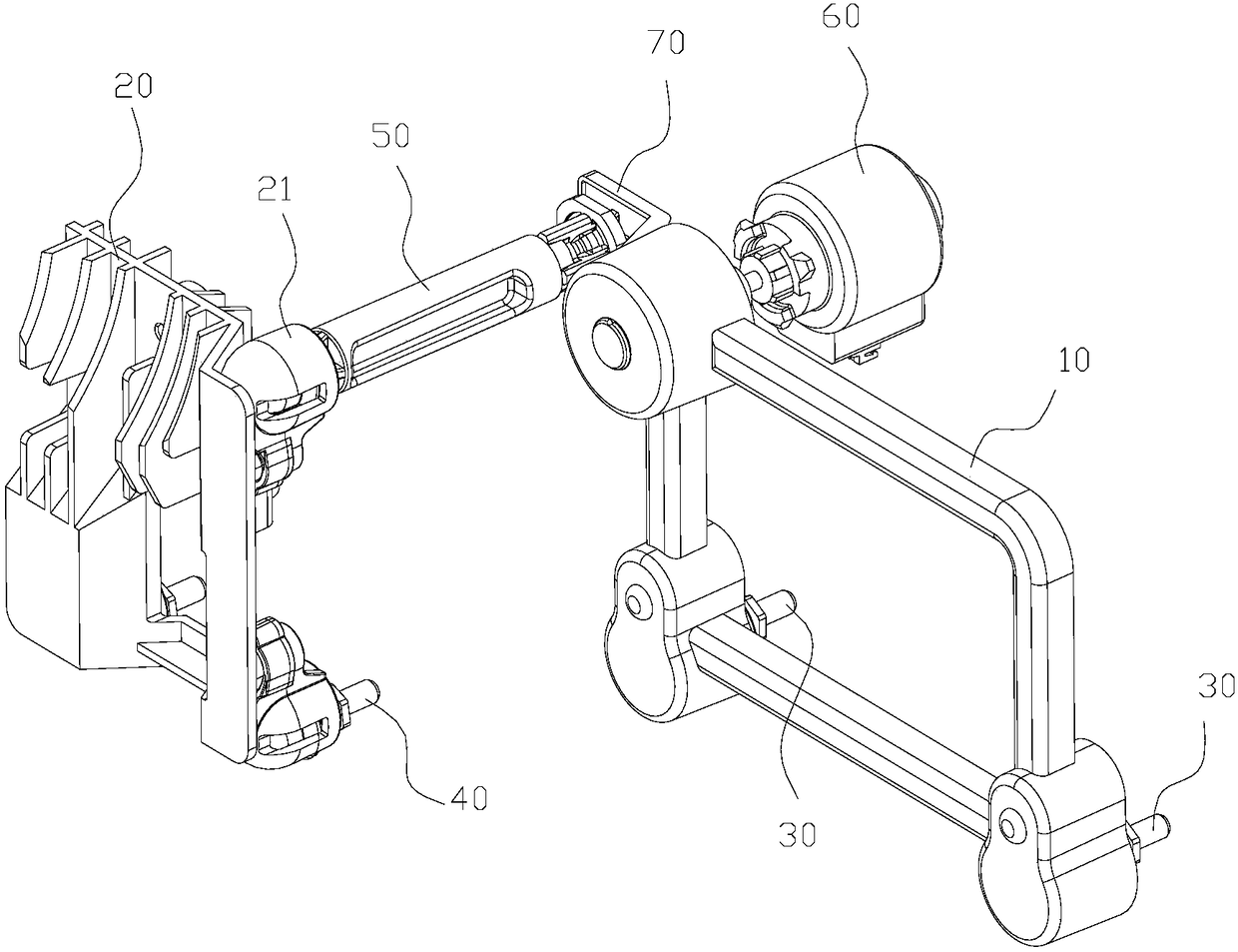
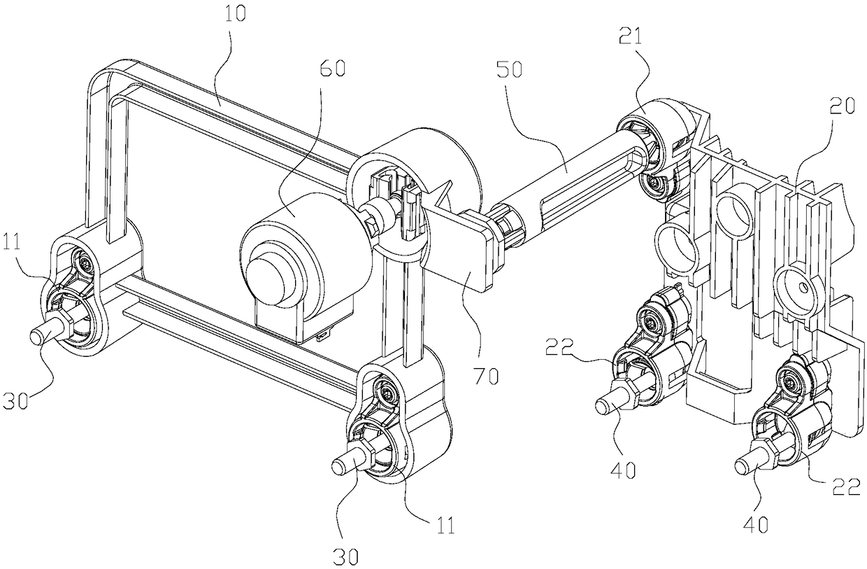
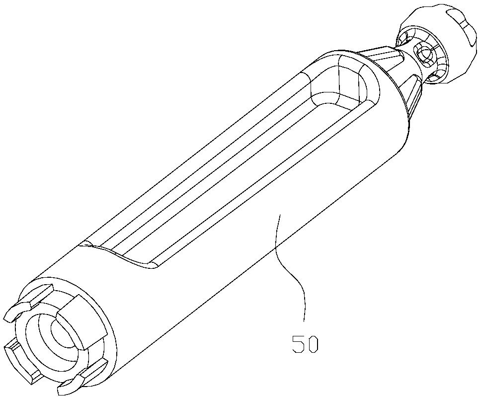
[0018] A far and low beam linkage dimming mechanism, comprising a low beam bracket 10 and a high beam bracket 20, wherein one side of the low beam bracket 10 is rotatably matched with the first dimming screw 30, and one side of the high beam bracket 20 is matched with the second dimming screw 30. The light screw 40 is rotated and matched, and the low beam bracket 10 and the high beam bracket 20 are connected by a linkage rod 50, and the linkage rod 50 is perpendicular to the low beam bracket 10 and the high beam bracket 20 at the same time, and the extension and contraction of the low beam bracket 10 and the dimming motor 60 The rods are vertically connected, and the dimming motor 60 can simultaneously drive the low beam bracket 10 to rotate around the side where the first dimming screw 30 is located, drive the high beam bracket 20 to rotate around the side where the second dimming screw 40 is loca...


PUM


Abstract

The invention relates to the technical field of headlamp dimming, in particular to a distance light and short-distance light linked dimming mechanism. The distance light and short-distance light linked dimming mechanism comprises a short-distance light bracket and a short-distance light bracket, wherein one side of the short-distance light bracket is in rotary fit to a first dimming screw, one side of the distance light bracket is in rotary fit to a second dimming screw, the short-distance light bracket and the distance light bracket are connected through a linking rod, the linking rod is perpendicular to the short-distance light bracket and the distance light bracket simultaneously, the short-distance light bracket is perpendicularly connected to a telescopic rod of a dimming motor, the dimming motor can drive the short-distance light bracket to rotate around the side of the first dimming screw and drive the distance light bracket to rotate around the side of the second dimming screwsimultaneously, and the rotating radiuses, directions and angles are same; after the dimming motor receives a signal, the telescopic rod of the dimming motor stretches out or retracts, so as to drivethe short-distance light bracket and the distance light bracket to rotate, so that the dimming function is achieved effectively. The whole structure is relatively compact, and the linking rod is shortened, so that the space range of the whole mechanism is reduced effectively, and miniaturization of a headlamp is promoted.

Description

technical field [0001] The invention relates to the technical field of headlight dimming, in particular to a linkage dimming mechanism for far and low beams. Background technique [0002] GB4785_2007 stipulates that the car needs to have a headlight dimming device to compensate for the change in the slope of the low beam cut-off line caused by the change of the car load. The high beam and low beam light types need to maintain a specific relationship on the light distribution screen, that is, when the dimming device adjusts the low beam inclination, the high beam is generally adjusted at the same time to maintain the relative position between the two. The high-beam and low-beam linkage dimming mechanism is a device that simultaneously adjusts the high-beam and low-beam systems, which can ensure the consistency of the adjustment of the high-beam and low-beam systems. [0003] However, the current common linkage adjustment structure is mostly used in halogen and xenon headligh...

Claims


Application Information

Patent Timeline
Patent Type & Authority Applications(China)
IPC IPC(8): F21S41/60F21V14/00
CPCF21V14/00
Inventor 严帅包国栋昌进孟庆恩陆春艳
Owner CHANGZHOU XINGYU AUTOMOTIVE LIGHTING SYST
Learn More