Numerical control solid wood cutting, milling and sawing machine

A technology of solid wood and sawing machine, which is applied in the field of wood processing, and can solve the problems of users' troubles, the inability to effectively discharge wood chips, and the sticking of wood chips to the blade, etc.

Active Publication Date: 2018-10-23
南京雄锋工具有限公司
View PDF6 Cites 1 Cited by
  • Summary
  • Abstract
  • Description
  • Claims
  • Application Information

AI Technical Summary

Problems solved by technology

The solid wood cutting milling machine is improved according to the principle of the computer engraving machine. It lengthens the milling cutter and fixes the upper and lower ends of the milling cutter. By driving the milling cutter to select and realize milling wood, but when milling, the milling cutter It can only rotate and move, resulting in greater resistance from the wood, and the generated wood chips cannot be effectively discharged. For example, when milling wood with high hardness and strength, high temperature will be generated, and the wood chips generated by milling will stick to the blade, and it will be easy to generate high temperature Appears to burn the knife or burn the wood
[0004] The above-mentioned several kinds of solid wood cutting tools all have deficiencies, cannot be well used by users, and cause great troubles to users. In view of this, the inventor proposes the following technical solutions

Method used


Image

  • Numerical control solid wood cutting, milling and sawing machine
  • Numerical control solid wood cutting, milling and sawing machine
  • Numerical control solid wood cutting, milling and sawing machine

Examples


Embodiment Construction

[0023] The present invention will be further described below in conjunction with specific embodiments and accompanying drawings.

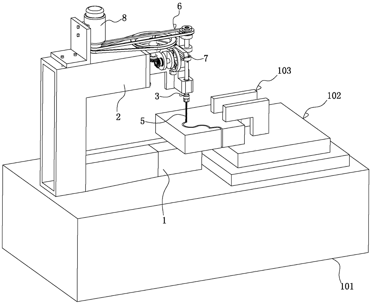
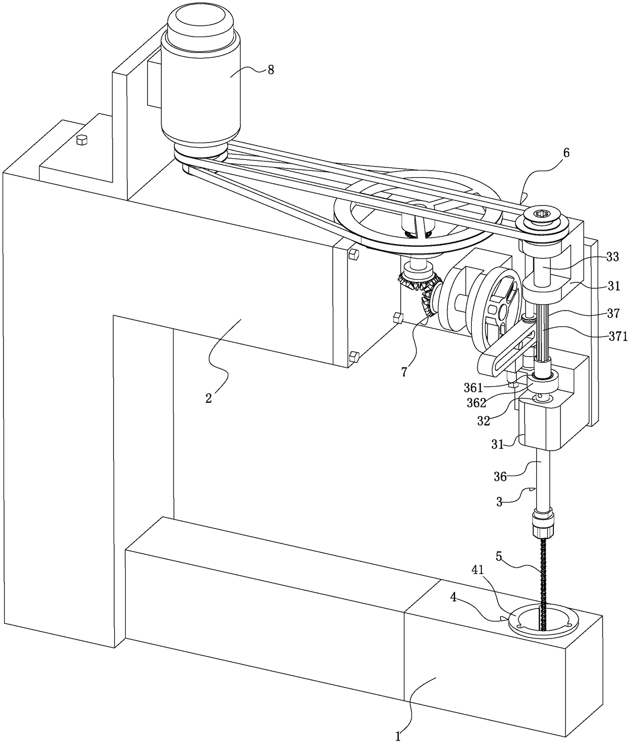
[0024] See Figure 1-6 As shown, it is a CNC solid wood milling and sawing machine, which includes: a base 1 and a machine head 2 installed on the base 1, a spindle module 3 installed on the machine head 2, and a rotatable Up and down sliding module 4, a cylindrical milling saw blade 5 fixedly installed between the main shaft module 3 and the rotatable up and down sliding module 4, a rotary drive installed on the head 2 and used to drive the main shaft module 3 to rotate The mechanism 6 and the up and down sliding drive mechanism 7 installed on the machine head 2 and used to drive the spindle module 3 to move back and forth up and down, the rotary drive mechanism 6 and the up and down sliding drive mechanism 7 share a motor 8 as a power device. When the present invention works, since the cylindrical milling saw cutter 5 is fixedly installed betwee...


PUM


Abstract

The invention discloses a numerical control solid wood cutting, milling and sawing machine. The numerical control solid wood cutting, milling and sawing machine comprises a base, a handpiece mounted on the base, a spindle module mounted on the handpiece, a rotatable up-down sliding module mounted on the base, a cylindrical milling and sawing tool fixedly mounted between the spindle module and therotatable up-down sliding module, a rotary driving mechanism which is mounted on the handpiece and used for driving the spindle module to rotate, and an up-down sliding driving mechanism which is mounted on the handpiece and used for driving the spindle module to reciprocally move up and down. The rotary driving mechanism and the up-down sliding driving mechanism share a motor as a power device. Due to the fact that the cylindrical milling and sawing tool reciprocally moves up and down while rotating, the functions of milling and sawing can be simultaneously achieved, wood can be rapidly cut,the machine is high in speed and high in operation efficiency, arc shapes with smaller radii can be milled, wood waste can be avoided, and different cutting processing demands are met; and the cylindrical milling and sawing tool can rapid take produced wood chips out, that is, the produced wood chips can be effectively discharged.

Description

Technical field: [0001] The invention relates to the technical field of wood processing, in particular to a numerical control solid wood cutting milling and sawing machine. Background technique: [0002] In the prior art, solid wood cutting tools include: band saws, jigsaws, solid wood cutting milling machines and computer engraving machines. [0003] The above-mentioned solid wood cutting tools are all used for sawing or milling various wood objects into arcs, special shapes or other shapes. However, due to the width of the saw blade of the band saw, the arc radius of the saw cannot be less than 5cm, and the sawn wood cutting surface has uneven stripes, which require secondary processing or rough grinding. Some workpieces have an arc cutting surface smaller than 5cm requires manual sawing to clear the corners. The jigsaw uses a crankshaft connecting rod to drive a wire saw with a diameter of 2-3cm to saw wood. Since the wire saw is soft, the installation needs to be tight...

Claims


Application Information

Patent Timeline
Patent Type & Authority Applications(China)
IPC IPC(8): B27C5/02B27G3/00
CPCB27C5/02B27G3/00Y02P70/10
Inventor 郭华伟
Owner 南京雄锋工具有限公司
Why Eureka
Try Eureka