
Automatic welding machine for motor cooling fins of new energy vehicle

A technology of new energy vehicles and automatic welding machines, applied in welding equipment, auxiliary welding equipment, welding/cutting auxiliary equipment, etc., can solve the problems of manual welding, high labor intensity, low work efficiency, etc., achieve fast and effective welding, reduce Effects of labor intensity, efficiency improvement and product quality

Inactive Publication Date: 2018-10-23
夏文斌
View PDF7 Cites 0 Cited by
  • Summary
  • Abstract
  • Description
  • Claims
  • Application Information

AI Technical Summary

Problems solved by technology

[0003] The purpose of the present invention is to provide an automatic welding machine for motor heat sinks of new energy vehicles, to solve the problem that the current heat sinks on the surface of the machine base proposed in the background technology are manually welded, which has low work efficiency, high labor intensity, and poor product quality. stability problem

Method used


Image

  • Automatic welding machine for motor cooling fins of new energy vehicle
  • Automatic welding machine for motor cooling fins of new energy vehicle
  • Automatic welding machine for motor cooling fins of new energy vehicle

Examples


Embodiment Construction

[0018] The following will clearly and completely describe the technical solutions in the embodiments of the present invention with reference to the accompanying drawings in the embodiments of the present invention. Obviously, the described embodiments are only some, not all, embodiments of the present invention. Based on the embodiments of the present invention, all other embodiments obtained by persons of ordinary skill in the art without making creative efforts belong to the protection scope of the present invention.

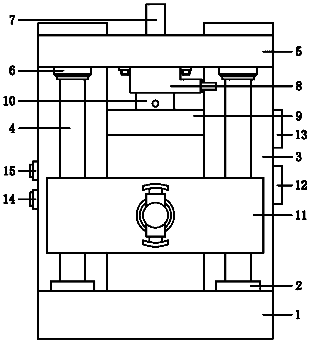
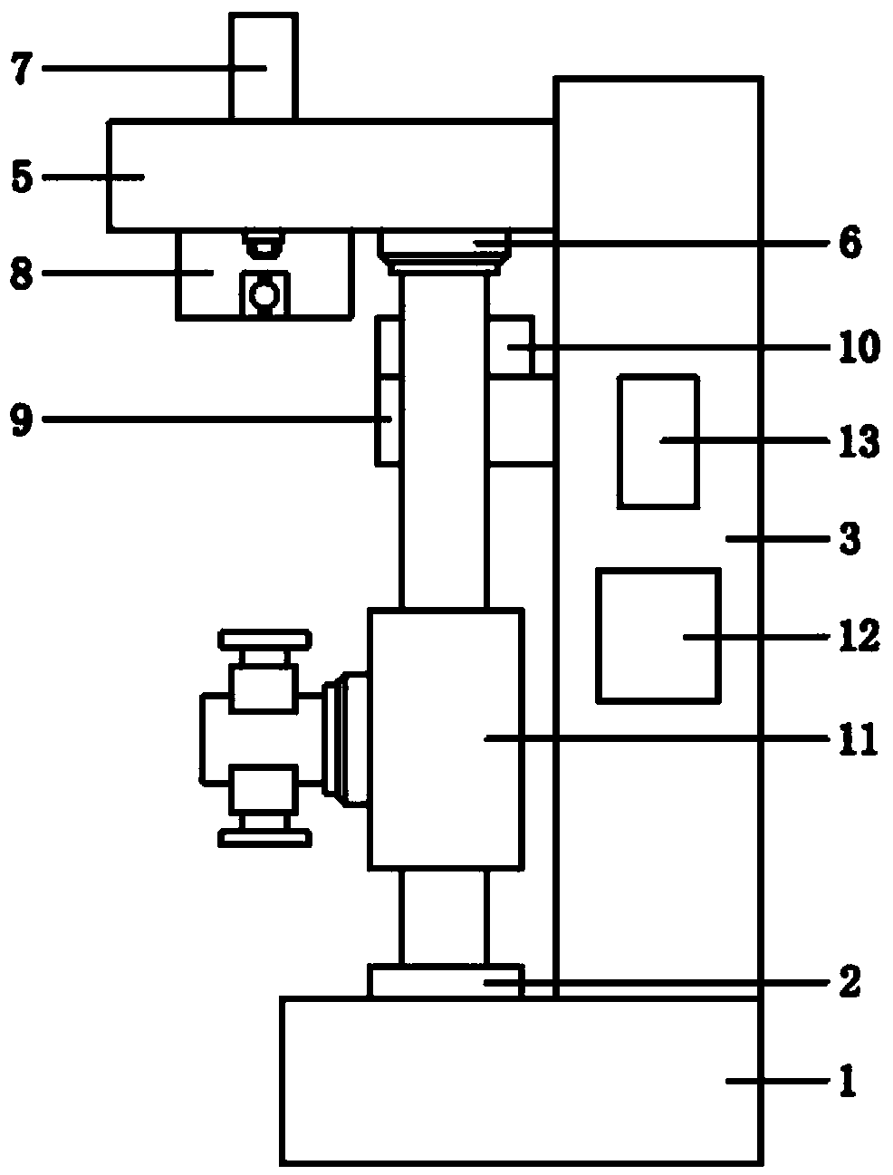
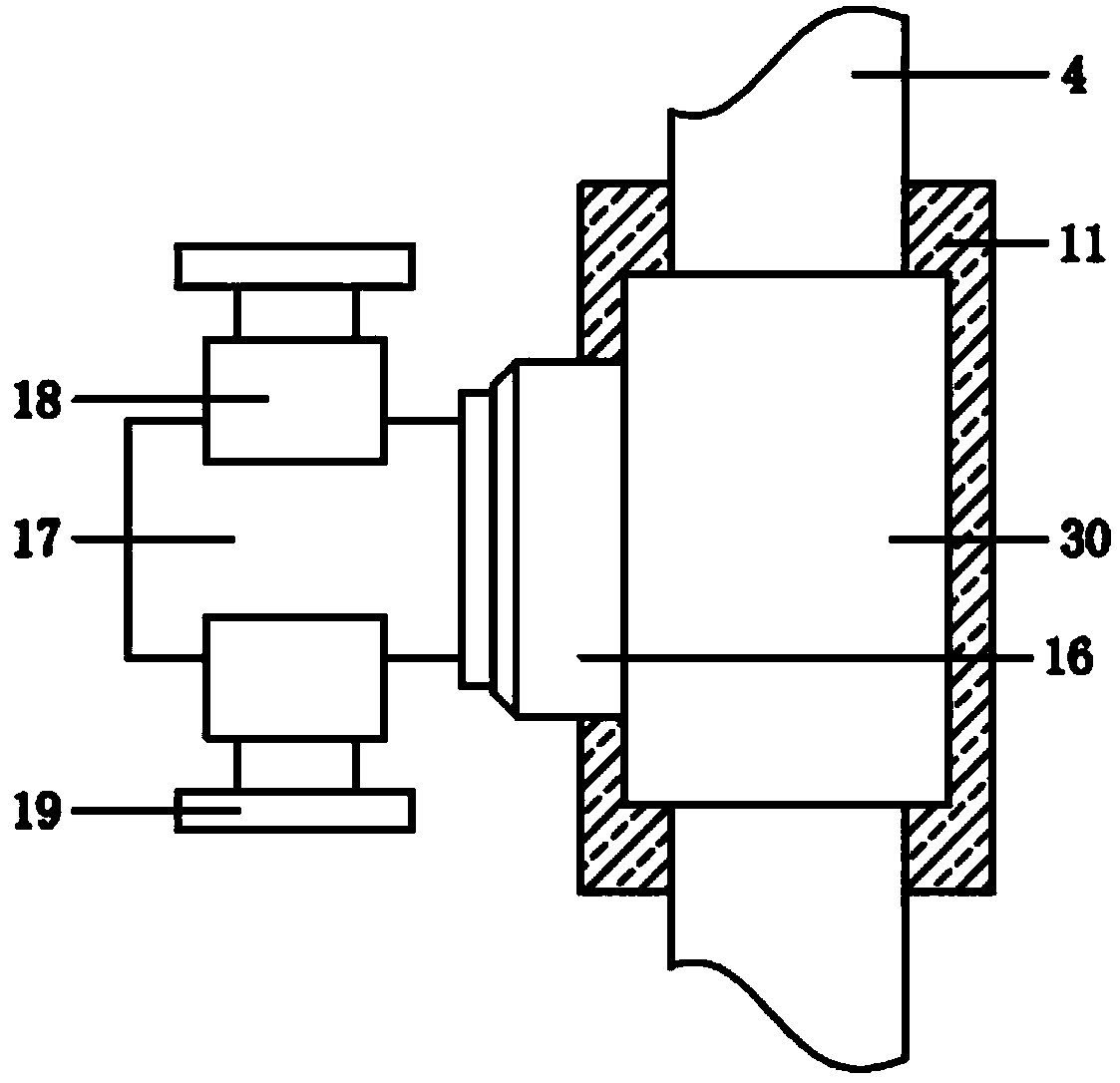
[0019] see Figure 1-7 , the present invention provides a technical solution: an automatic welding machine for motor cooling fins of new energy vehicles, including a base 1, the left and right sides of the top of the base 1 are connected with a bearing seat 2 and a support seat 3, two bearing seats 2 At the front end of the support base 3, the tops of the two bearing bases 1 are plugged with lead screws 4, and the tops of the front surfaces of the two support ...


PUM


Abstract

The invention discloses an automatic welding machine for motor cooling fins of new energy vehicles and belongs to the technical field of welding machines. The automatic welding machine comprises a base. Bearing blocks and supporting seats are connected to the left and right sides of the top of the base correspondingly. The two bearing blocks are arranged at the front ends of the supporting seats.Lead screws are connected to the tops of the bearing blocks in a penetrating mode. A cross beam is transversely welded to the tops of the front surfaces of the two supporting seats. First motors are connected to the left and right sides of the bottom of the cross beam in a penetrating mode. Output shafts of the bottoms of the two first motors are connected with the corresponding lead screws. A first hydraulic telescopic rod is connected to the middle end of the top of the cross beam in a penetrating mode. A discharge box is mounted at the middle end of the bottom of the cross beam. The automatic welding machine implements automatic discharging through the hydraulic telescopic rod, conducts accurate locating through a PLC and a servo motor, can rapidly and effectively conduct welding on thecooling fins without manual welding, improves the welding efficiency and product quality and reduces the labor intensity.

Description

technical field [0001] The invention relates to the technical field of welding machines, in particular to an automatic welding machine for motor radiators of new energy vehicles. Background technique [0002] The motor usually includes a frame, a stator, a rotor, an end cover and other accessories. The function of the frame is to fix the stator and the front and rear end covers to support the rotor, and to play the role of protection and heat dissipation. The frame is mainly carried out through its own surface. For heat dissipation, multiple heat sinks are generally welded on the outer wall of the machine base to improve heat dissipation. At present, the heat sink on the surface of the base is manually welded, which has low work efficiency, high labor intensity and unstable product quality. Contents of the invention [0003] The purpose of the present invention is to provide an automatic welding machine for motor heat sinks of new energy vehicles, to solve the problem tha...

Claims


Application Information

Patent Timeline
IPC IPC(8): B23K37/00B23K37/02B23K37/04
Inventor 夏文斌
Owner 夏文斌
Learn More