
Simplified tube-shell type fluid mixer

A fluid mixing, shell-and-tube technology, applied in the direction of fluid mixers, mixers, chemical instruments and methods, etc., can solve the problems of large pressure loss, unfavorable engine fuel economy, etc., to reduce pressure loss and improve processing convenience performance, high mixing efficiency

Pending Publication Date: 2018-10-23
DONGFENG COMML VEHICLE CO LTD
View PDF5 Cites 2 Cited by
  • Summary
  • Abstract
  • Description
  • Claims
  • Application Information

AI Technical Summary

Problems solved by technology

[0004] The purpose of the present invention is to provide a simplified shell-and-tube fluid mixer for the problems of large pressure loss and unfavorable fuel economy of the engine in the existing mixer.

Method used


Image

  • Simplified tube-shell type fluid mixer
  • Simplified tube-shell type fluid mixer
  • Simplified tube-shell type fluid mixer

Examples


Embodiment Construction

[0020] The present invention will be further described in detail below in conjunction with the accompanying drawings and specific embodiments.

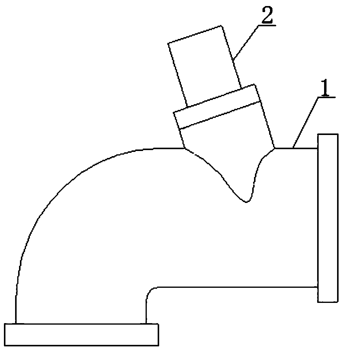
[0021] see Figure 1 to Figure 2 , a simplified shell-and-tube fluid mixer, which is suitable for mixing gas, EGR and other gases or other fluids, including a main flow pipe 1 and an EGR pipe 2 . The EGR pipe outlet end 6 of the EGR pipe 2 extends into the inner chamber of the main flow pipe 1 from the side wall of the main flow pipe 1, and the EGR pipe outlet end 6 faces away from the main flow pipe 1 airflow direction, that is, the EGR pipe outlet end 6 faces away from the inlet 3 of the main flow pipe.

[0022] see Figure 1 to Figure 2 , the EGR pipe outlet end 6 is a chamfered plane, and the chamfered plane is perpendicular to the plane formed by the axis of the main flow pipe 1 and the axis of the EGR pipe 2 . Moreover, the height of the chamfered surface at the outlet end 6 of the EGR pipe is greater than 0.5 times the diame...


PUM


Abstract

The invention discloses a simplified tube-shell type fluid mixer. The simplified tube-shell type fluid mixer comprises a main flow tube (1) and an EGR (Exhaust Gas Recirculation) tube (2), wherein anEGR tube outlet end (6) of the EGR tube (2) extends into an inner cavity of the main flow tube (1) from the side wall of the main flow tube (1), and is opposite to the airflow direction of the main flow tube (1). The EGR tube outlet end (6) is an inclined section which is vertical to a plane formed by the axis of the main flow tube (1) and the axis of the EGR tube (2); the height of the inclined section of the EGR tube outlet end (6) is larger than the diameter of the main flow tube (1) by more than 0.5 time. The simplified tube-shell type fluid mixer disclosed by the invention has the beneficial effects that airflow generates suctioning effect for the EGR tube outlet end (6) to form negative pressure, so that the pressure loss of the EGR side is reduced and the EGR driving force is improved.

Description

technical field [0001] The invention relates to a mixer, in particular to a simplified shell-and-tube fluid mixer, which belongs to the technical field of fluid mixing. Background technique [0002] The fluid mixer is mainly used to mix the two fluids as evenly as possible according to the required ratio. The Chinese invention patent application "A Mixer for Integrated Gas and EGR" (patent application number: CN201511019825.9) introduces a Mixer unit integrating gas and EGR. Chinese utility model patent "A Double-chamber Integrated EGR Mixer" (patent application number: CN201520761867.9) introduces a double-chamber integrated EGR mixer, in which an independent beam structure is designed to connect the gas and EGR chambers respectively body to achieve the purpose of integrating gas and EGR mixing. Chinese invention patent application "Integrated EGR Mixer" (patent application number: CN201510486605.0) introduces an integrated EGR mixer with a double-beam structure. Mixing ...

Claims


Application Information

Patent Timeline
Patent Type & Authority Applications(China)
IPC IPC(8): B01F5/04
CPCB01F25/311
Inventor 徐敏李卫国王必璠王振红张少华陈珏陈丽丽覃欢欢
Owner DONGFENG COMML VEHICLE CO LTD
Learn More