Method for automatically controlling air conditioner cleaning function
An air-conditioning and cleaning technology, applied in air-conditioning systems, heating methods, space heating and ventilation, etc., can solve the problem of low degree of cleanness and intelligence of air-conditioning, and achieve the effect of improving user experience, ensuring intelligence and accurate detection
- Summary
- Abstract
- Description
- Claims
- Application Information
AI Technical Summary
Problems solved by technology
Method used
Image
Examples
Embodiment 1
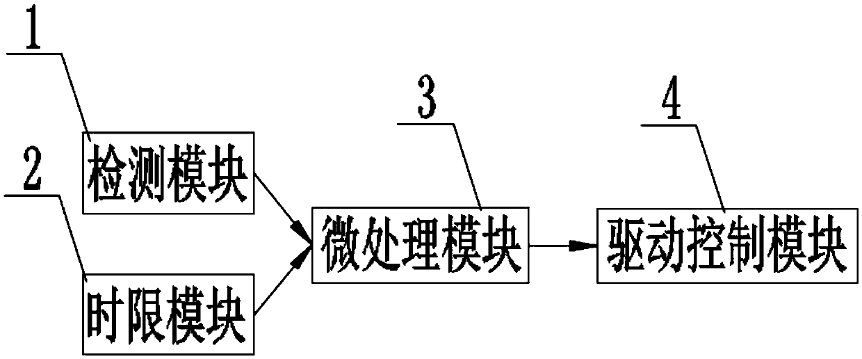
[0036] figure 1 A functional schematic diagram of the air-conditioning self-cleaning system is shown, and only parts related to the embodiment of the present invention are shown for convenience of description.
[0037] The air conditioner self-cleaning system provided in this embodiment includes a detection module 1, a time limit module 2, a microprocessing module 3 and a drive control module 4, the detection module 1, the time limit module 2, the drive control module 4 and the drive control module The microprocessing module 3 data connection.
[0038] The detection module 1 detects the accumulation thickness of pollutants on the evaporator (between the fins) of the air conditioner and the filter, and converts the accumulation thickness value of pollutants into a corresponding voltage value, that is, the pollution detection value V, and the The pollution detection value V is sent to the micro-processing module 3 . It is worth pointing out that the detection module 1 can also...
Embodiment 2
[0043] In this embodiment, the detection module 1 includes a first pole plate 11 and a second pole plate 12, which are co-located on an evaporator or a filter, and a voltage detector is connected to the first pole plate 11 and the second pole plate 12. The pole plate 12 is electrically connected, the voltage detector is electrically connected with the microprocessing module 3, and the voltage detector detects the potential difference between the first pole plate 11 and the second pole plate 12, that is, pollution detection Value V.
[0044] In this embodiment, the first pole plate 11 and the second pole plate 12 arranged in relative cooperation between the evaporator and the filter screen are connected with the first pole plate 11 and the second pole plate. The voltage detector electrically connected to the plate 12 realizes the detection of capacitance information on the evaporator or filter, wherein the voltage detector controls the voltage between the first pole plate 11 an...
Embodiment 3
[0055] Such as image 3 as shown, image 3 It is the structural diagram of the present embodiment of the detection module; the third embodiment is further improved on the basis of the second embodiment, and the specific improvement is that the first pole plate 11 and the second pole plate 12 are arranged in the same Adjacent to the evaporator fins 5, and preferably, one of the first pole plate 11 and the second pole plate 12 is arranged at the bottom end of the adjacent evaporator fins 5, the The other of the first pole plate 11 and the second pole plate 12 is arranged on the top of the adjacent fin 5 of the evaporator, that is, the first pole plate 11 and the second pole plate 12 will be connected to each other respectively. The two ends adjacent to the fins 5 of the evaporator are connected.
[0056] By arranging the first pole plate 11 and the second pole plate 12 at the two ends of the adjacent fins 5, the first pole plate 11 and the second pole plate 12 are formed The ...
PUM
 Abstract
Description
Claims
Application Information
 - R&D Engineer
- R&D Manager
- IP Professional
- Industry Leading Data Capabilities
- Powerful AI technology
- Patent DNA Extraction
Browse by: Latest US Patents, China's latest patents, Technical Efficacy Thesaurus, Application Domain, Technology Topic, Popular Technical Reports.
© 2024 PatSnap. All rights reserved.Legal|Privacy policy|Modern Slavery Act Transparency Statement|Sitemap|About US| Contact US: help@patsnap.com


