
Connecting rod type crankshaft-free engine

A technology without crankshaft and engine, applied in the field of fuel engine and connecting rod type crankless engine, can solve the problems of large exhaust gas emission, insufficient cylinder combustion, low internal combustion engine heat engine efficiency, etc., to achieve high heat engine efficiency, not easy to slip, transmission great effect

Pending Publication Date: 2018-10-19
苏州智一新能源动力系统有限公司
View PDF10 Cites 1 Cited by
  • Summary
  • Abstract
  • Description
  • Claims
  • Application Information

AI Technical Summary

Problems solved by technology

[0003] The purpose of the present invention is to provide a connecting rod type crankshaftless engine to solve the problems of low thermal efficiency of existing internal combustion engines, insufficient cylinder combustion, and large exhaust gas emissions

Method used


Image

  • Connecting rod type crankshaft-free engine
  • Connecting rod type crankshaft-free engine
  • Connecting rod type crankshaft-free engine

Examples


Embodiment 1

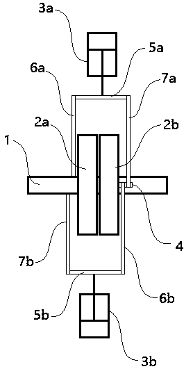
[0037] see figure 1 with figure 2 Shown, a kind of connecting rod type crankshaftless engine comprises output shaft 1, first one-way wheel 2a, second one-way wheel 2b, first piston 3a and second piston 3b; Said first one-way wheel 2a and The second one-way wheels 2b are both sleeved on the output shaft 1, the effective rotation directions of the first one-way wheels 2a and the second one-way wheels 2b are the same, and the first one-way wheels 2a and the left or right end of the outer surface of the second one-way wheel 2b are provided with a short connecting shaft 4; the first piston 3a and the second piston 3b are respectively arranged on the upper and lower sides of the output shaft 1 , the piston rod of the first piston 3a is provided with a first long connecting shaft 5a, the piston rod of the second piston 3b is provided with a second long connecting shaft 5b, the first long connecting shaft 5a and the first long connecting shaft 5a The two long connecting shafts 5b a...

Embodiment 2

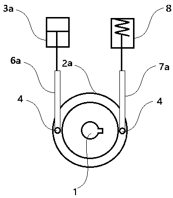
[0040] see image 3 As shown, a connecting rod type crankshaftless engine includes an output shaft 1, a first one-way wheel 2a, a first piston 3a and an air spring 8; the first one-way wheel 2a is sleeved on the output shaft 1 , the left and right ends of the outer surface of the first one-way wheel 2a are respectively provided with a short connecting shaft 4; the first piston 3a is located above or below the short connecting shaft 4, and is connected to The rod 6a is connected to the short connecting shaft 4, the air spring 8 is located above or below the other short connecting shaft 4, and is connected to the short connecting shaft through the first driven connecting rod 7a. 4 connections.

[0041] Further, when the effective rotation direction of the first one-way wheel 2a is counterclockwise, the first piston 3a is arranged above the short connecting shaft 4 on the left side or the short connecting shaft 4 on the right side. Below the connecting shaft 4, the air spring 8...

Embodiment 3

[0043] see Figure 4 with Figure 5 As shown, the first one-way wheel 2a and the second one-way wheel 2b have the same structure, and both include an output disc 201, a transmission wheel 202, a one-way locking mechanism and a supporting bearing mechanism. The transmission wheel 202 is sheathed outside the output disc 201, and the output disc 201 is detachable. A shaft mounting hole 203 and a shaft positioning groove 204 for mounting the output shaft are provided in the center of the output disc 201 .

[0044] Between the output disk 201 and the transmission wheel 202, there are 4-8 one-way locking mechanisms. Each one-way locking mechanism includes a wedge-shaped groove 205 provided on the circumference of the output disk 201, the bottom surface, front side, rear side and inner side of the wedge-shaped groove 205 are closed surfaces, and the wedge-shaped groove The outer surface of 205 is an open surface, and the bottom surface, front side, rear side, and inner surface of ...


PUM


Abstract

The invention discloses a connecting rod type crankshaft-free engine comprising an output shaft. The output shaft is provided with a first unidirectional wheel and a second unidirectional wheel, and short connecting shafts are arranged at the left ends or the right ends of the outer side faces of the two unidirectional wheels correspondingly; a first piston and a second piston are arranged on theupper side and the lower side of the output shaft, and a first long connecting shaft and a second long connecting shaft are arranged on piston rods of the two pistons correspondingly; the front end and the rear end of the first long connecting shaft are connected with the short connecting shaft located on the first unidirectional wheel and the short connecting shaft located on the second unidirectional wheel through a first transmission connecting rod and a first driven connecting rod correspondingly; and the front end and the rear end of the second long connecting shaft are connected with theshort connecting shaft located on the first unidirectional wheel and the short connecting shaft located on the second unidirectional wheel through a second driven connecting rod and a second transmission connecting rod correspondingly. The connecting rod type crankshaft-free engine adopts a connecting rod type transmission mechanism and fully utilizes the unidirectional locking characteristic ofthe unidirectional wheels, thus rotating of an output disc is achieved, and the connecting rod type crankshaft-free engine has the advantages of simple structure, small size, low cost, reliable work,high heat engine efficiency, flexible application, high universality and the like.

Description

technical field [0001] The invention belongs to the technical field of automobile engines, and relates to a fuel engine, in particular to a connecting rod type crankshaftless engine. Background technique [0002] At present, fuel engines all over the world are reciprocating engines using a crankshaft as a transmission mechanism. The design of the reciprocating engine is complex, and the noise is loud during acceleration, especially in the dead zone of the piston, and the crankshaft will lose power at 0 degrees and 180 degrees. So far, all motorcycles and automobile internal combustion engines have adopted the above-mentioned scheme, and their heat engine efficiency is about 25% at the highest, which leads to a serious situation in the tail row of automobiles under variable power operation. Contents of the invention [0003] The object of the present invention is to provide a connecting-rod type crankshaftless engine to solve the problems of low heat engine efficiency, ins...

Claims


Application Information

Patent Timeline
Patent Type & Authority Applications(China)
IPC IPC(8): F02B75/24F02B75/32
CPCF02B75/24F02B75/32F02B2075/1808
Inventor 樊朝晖左臣伟
Owner 苏州智一新能源动力系统有限公司
Learn More