
Bearing and energy-dissipation difunctional corrugated steel plate wall

A corrugated steel plate, dual-function technology, applied in the direction of walls, building components, building structures, etc., can solve the problems of low vertical bearing capacity, low lateral and buckling bearing capacity, limited hysteretic performance, and steel plate wall deformation, etc. Reduced welding workload, high anti-side and energy efficiency, and reduced plate thickness

Pending Publication Date: 2018-10-19
上海史狄尔建筑减震科技有限公司
View PDF10 Cites 10 Cited by
  • Summary
  • Abstract
  • Description
  • Claims
  • Application Information

AI Technical Summary

Problems solved by technology

However, due to the small out-of-plane stiffness of the flat steel plate, out-of-plane buckling will occur under the action of a small horizontal force, resulting in low stiffness and limited hysteretic performance.
Most of the built-in structures of steel plate shear walls in the prior art are flat steel plates, and their vertical bearing capacity, lateral resistance and buckling capacity are all low. After an earthquake, the steel plate wall is prone to deformation and energy consumption.
If the deformation is not serious, it needs to be repaired before it can be used again; but if the deformation is serious, it cannot be repaired, and the built-in steel plate needs to be replaced, which will increase the cost
On this basis, if out-of-plane restraint plates or stiffeners are used to improve the out-of-plane stiffness of such components, there are still a series of problems such as reduced economy and complex processing.

Method used


Image

  • Bearing and energy-dissipation difunctional corrugated steel plate wall
  • Bearing and energy-dissipation difunctional corrugated steel plate wall
  • Bearing and energy-dissipation difunctional corrugated steel plate wall

Examples


Embodiment Construction

[0018] In order to further illustrate the present invention, the present invention will be described in detail below in conjunction with the accompanying drawings and embodiments, but they should not be construed as limiting the protection scope of the present invention.

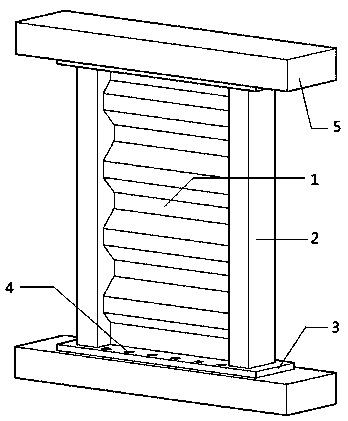
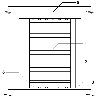
[0019] like figure 1 , 2 As shown, a corrugated steel plate wall with dual functions of load-bearing and energy-dissipating in the present invention includes: an anti-seismic energy-dissipating element located in the center, that is, a non-buckling corrugated steel plate energy-dissipating wall 1 and square steel tube concrete column members 2 on both sides, and a buckling-free corrugated steel plate The energy-dissipating wall 1 is connected to the square steel tube concrete column members 2 on the left and right sides by welding. The upper and lower ends of the square steel tube concrete column members 2 are respectively welded with a bottom plate 3, and the bottom plate 3 is provided with bolt holes 4. Th...


PUM


Abstract

The invention discloses a bearing and energy-dissipation difunctional corrugated steel plate wall. The bearing and energy-dissipation difunctional corrugated steel plate wall comprises a buckling-freecorrugated steel plate energy-dissipation wall located in the center and square steel pipe concrete column members located at the two sides, the buckling-free corrugated steel plate energy-dissipation wall is welded to the square steel pipe concrete column members at the left side and the right side, the upper ends and the lower ends of the square steel pipe concrete column members are welded tobase plates respectively, and the base plates are fixed to frame beams. The bearing and energy-dissipation difunctional corrugated steel plate wall is connected with a main body structure through bolts, the convenience and assembly degree of on-spot installation are improved, and the on-spot welding workload is reduced. The bearing and energy-dissipation difunctional corrugated steel plate wall integrates load bearing and earthquake-resistance energy dissipation, and the shear capacity and the stability of the structure can be improved; when the bearing and energy-dissipation difunctional corrugated steel plate wall is subjected to plastic energy dissipation, an additional damping ratio is provided, the response under a structure earthquake is reduced, the weight can also be borne, part ofupper vertical loads borne by the columns are shared, and the purpose that the wall has two functions is achieved.

Description

technical field [0001] The invention relates to the technical field of construction engineering, in particular to a corrugated steel plate wall with dual functions of load bearing and energy consumption. Background technique [0002] High-rise buildings will occupy an increasingly important position in the future construction industry, and the selection of lateral force-resistant structural components in high-rise buildings is very important. Traditional lateral force resistant structural components mainly include shear walls, steel supports, etc., but these can no longer meet the needs of super high-rise buildings for structural seismic capacity. In response to this situation, many new structural energy-dissipating components have emerged as the times require. Examples include viscous damped walls, buckling-resistant steel walls, and shear-type dampers. [0003] For steel plate walls, flat steel plates are generally used. However, due to the small out-of-plane stiffness ...

Claims


Application Information

Patent Timeline
IPC IPC(8): E04H9/02E04B1/98E04B2/56
CPCE04B1/98E04B2/56E04H9/021
Inventor 王海巍程荣杨肖
Owner 上海史狄尔建筑减震科技有限公司
Learn More