
Shaft tube end clamping mounting mechanism

A technology of installation mechanism and shaft tube, which is applied in metal processing, metal processing equipment, manufacturing tools, etc., can solve the problems of poor quality of shaft tube fixing, difficulty in ensuring the accuracy of installation level, difficulty in applying to various vehicle models, etc., and achieve structural design reasonable effect

Active Publication Date: 2018-10-19
南通天福机械有限公司
View PDF5 Cites 2 Cited by
  • Summary
  • Abstract
  • Description
  • Claims
  • Application Information

AI Technical Summary

Problems solved by technology

When the half shaft sleeve is installed on the car, it is necessary to install the half shaft sleeve horizontally and accurately on the drive axle housing of the car. During the installation process, it is necessary to ensure the levelness of the shaft tube so that the shaft tube can be installed accurately , It can also avoid the scratching and damage of the shaft tube during the installation process. The existing shaft tube installation method mainly adopts manual installation, the shaft tube is large in size and heavy in quality, and the existing automobile assembly mainly adopts the assembly line for assembly , so the height required for the shaft tube to be lifted is also high, which makes the work intensity of the workers during the installation process greater, and it is also difficult to ensure the horizontal accuracy of the installation of the shaft tube during the manual installation process, which affects the installation of the car drive axle assembly Quality, the existing shaft tube installation mechanism is complex in structure and troublesome to operate, it is difficult to meet the installation of shaft tubes of various sizes and specifications, and because the shaft tube is difficult to be firmly and stably clamped and fixed during the installation process, the fixing quality of the shaft tube Poor, the shaft tube is easy to fall off during the translation installation process, resulting in production safety accidents, and the existing shaft tube installation mechanism has a limited translation adjustment range for the shaft tube during the shaft tube installation process, making it difficult to apply to many Therefore, the existing shaft tube installation mechanism cannot meet the needs of installation and use

Method used


Image

  • Shaft tube end clamping mounting mechanism
  • Shaft tube end clamping mounting mechanism
  • Shaft tube end clamping mounting mechanism

Examples


Embodiment Construction

[0016] In order to further describe the present invention, the specific implementation of a shaft tube end clamping installation mechanism will be further described below in conjunction with the accompanying drawings. The following examples are explanations of the present invention and the present invention is not limited to the following examples.

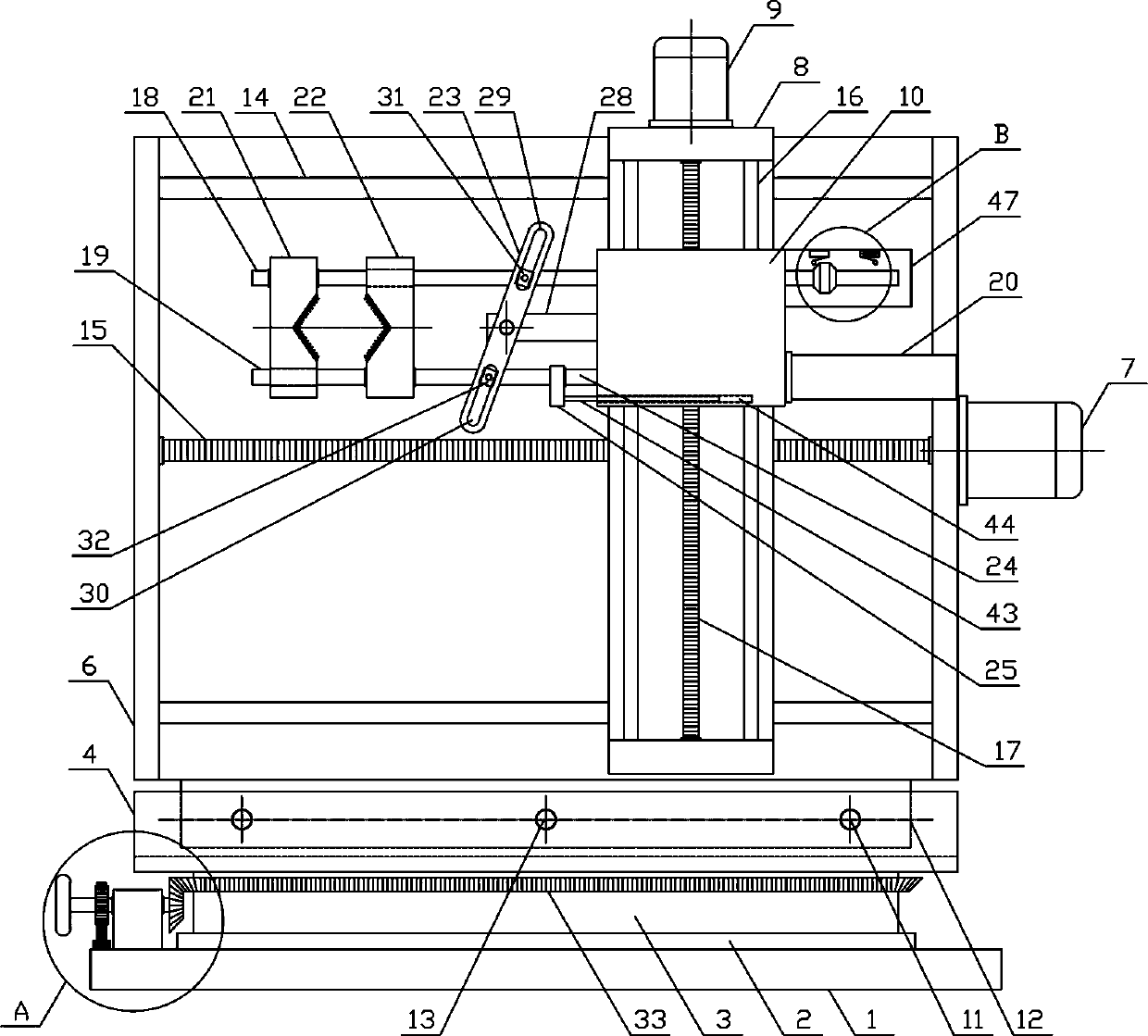
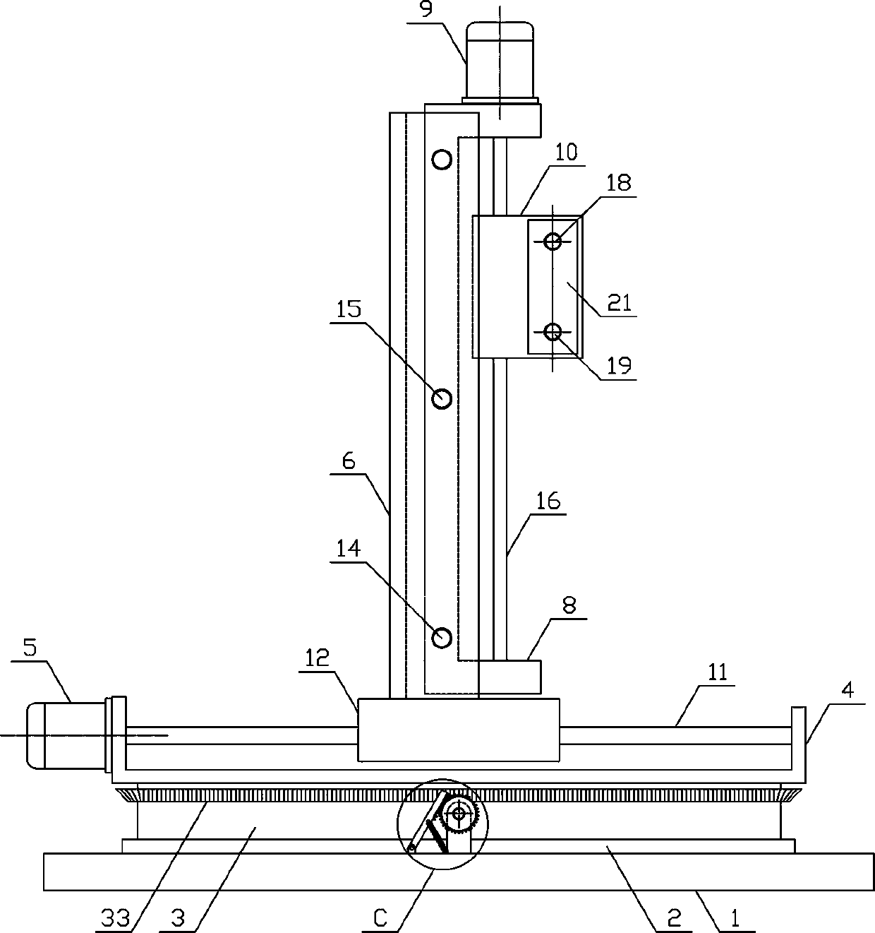
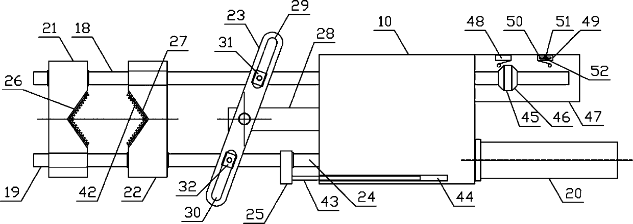
[0017] Such as figure 1 , figure 2 As shown, the clamping installation mechanism for the end of the shaft tube in the present invention includes a fixed base 1, a rotating base 2, an adjusting shaft 3, a lower translation bracket 4, a lower translation motor 5, an upper translation bracket 6, an upper translation motor 7, a lifting Bracket 8, lifting motor 9, lifting guide plate 10 and clamping mechanism, the upper side of the fixed base 1 is horizontally fixed with a rotating base 2, the adjusting shaft 3 is horizontally arranged on the upper side of the rotating base 2, and the lower side of the adjusting shaft 3 rotates horizo...


PUM


Abstract

The invention discloses a shaft tube end clamping mounting mechanism, belonging to the field of mounting auxiliary mechanical equipment. The lower side of an adjustment rotation shaft is horizontallyand rotatably arranged on a rotating base. A lower translation bracket is horizontally fixed on an upper side of the adjustment rotation shaft, and an upper translation bracket is vertically fixedly disposed on an upper side of a translation base. A lifting bracket is slidably disposed on an upper translation guide rod along the horizontal direction, and a lifting guide plate is slidably disposedon a lifting guide rod in the vertical direction. A tube clamping mechanism is horizontally disposed on one side of the lifting guide plate, the upper side of the adjustment rotation shaft is horizontally and fixedly provided with a rotating bevel gear. The upper side of a limiting rotation plate is fixedly provided with a limiting rack matched with a limiting gear, and a tension spring is disposed between the middle of the limiting rotation plate and a fixed base. Structural design of the shaft tube end clamping mounting mechanism is reasonable, the ends of shaft tubes of various sizes and specifications can be firmly clamped and fixed, and the shaft tubes can be smoothly adjusted and translated according to the needs, so that the shaft tube can be accurately mounted to meet the needs ofmounting and use.

Description

technical field [0001] The invention belongs to the field of installation auxiliary mechanical equipment, and in particular relates to a shaft tube end clamping installation mechanism, which is mainly used for translational installation of shaft tubes of various sizes and specifications. Background technique [0002] The structural shape of the axle tube is a cylindrical structure. There are many types of axle tubes, which are classified according to the use of the axle tubes, mainly including axle tubes, connecting axle tubes and transmission shaft tubes. Among them, the axle tubes are mainly used in automobiles. The semi-axle sleeve is an important part of the automobile drive axle assembly. It is integrated with the drive axle housing to fix the axial relative position of the left and right drive wheels, and supports the frame and all parts on it together. The quality of the assembly, and at the same time bear the road surface reaction force and moment transmitted from th...

Claims


Application Information

Patent Timeline
Patent Type & Authority Applications(China)
IPC IPC(8): B23P19/00B23P19/10
CPCB23P19/00
Inventor 朱海杰
Owner 南通天福机械有限公司
Learn More