Spraying paint exhaust gas adsorption treatment device

An adsorption treatment and waste gas technology, which is applied in gas treatment, dispersed particle filtration, membrane technology, etc., can solve the problem that the take-off pressure of the pressure relief valve cannot be adjusted according to the actual situation, the cost of activated carbon adsorbent is high, and the disassembly of the adsorption tank is inconvenient. Achieve the effect of reducing usage limitations, improving filtering effect, and improving flexibility

Inactive Publication Date: 2018-10-19
JIANGSU SELF ENVIRONMENTAL SCI & TECHCO
View PDF0 Cites 4 Cited by
  • Summary
  • Abstract
  • Description
  • Claims
  • Application Information

AI Technical Summary

Problems solved by technology

[0002] As we all know, the spray paint waste gas adsorption treatment device is an auxiliary device used to absorb and treat the waste gas generated during the painting process of workpieces and automobiles, so as to better reduce environmental pollution. It has been obtained in the field of paint spray waste gas treatment and environmental protection. It has been widely used; the existing spray paint waste gas adsorption treatment device includes an adsorption tank, an adsorption chamber is arranged inside the adsorption tank, and multiple groups of support screen frames are arranged horizontally inside the adsorption chamber, and multiple groups of support screen frames are filled with multiple A group of activated carbon adsorbents, the left front side, left rear side, right front side and right rear side of the bottom of the adsorption tank are welded with outriggers, the left end and top of the adsorption tank are respectively provided with an air inlet and an exhaust port, and the air inlet Both the exhaust port and the exhaust port communicate with the interior of the adsorption chamber, the air inlet and the exhaust port are respectively connected with an intake pipe and an exhaust pipe, and a centrifugal fan is connected with the air inlet pipe, and a pressure relief valve is connected with the left side of the top of the adsorption tank; When using the existing painting waste gas adsorption treatment device, firstly, the input end of the intake pipe is sent to the painting workshop, and then the centrifugal fan is electrically connected to the external power supply, and the centrifugal fan is turned on to suck the waste gas in the painting environment into the adsorption tank. After the activated carbon adsorbent is used for layer-by-layer adsorption treatment, it can be discharged after the treatment is completed; in the use of the existing spray paint waste gas adsorption treatment device, it is found that the activated carbon adsorbent cannot be desorbed and recycled after the adsorption is saturated, and the adsorption tank is disassembled It is inconvenient, and the cost of replacing the activated carbon adsorbent is high, which leads to high limitations in its use; at the same time, the take-off pressure of the pressure relief valve cannot be adjusted according to the actual situation, and the pressure inside the adsorption chamber cannot be kept constant, and the flexibility is poor; And it cannot pretreat the exhaust gas entering the adsorption chamber, resulting in larger particles directly entering the adsorption chamber, increasing the processing burden of activated carbon adsorbents, resulting in lower reliability in use

Method used


Image

  • Spraying paint exhaust gas adsorption treatment device
  • Spraying paint exhaust gas adsorption treatment device
  • Spraying paint exhaust gas adsorption treatment device

Examples


Embodiment Construction

[0021] The specific implementation manners of the present invention will be further described in detail below in conjunction with the accompanying drawings and embodiments. The following examples are used to illustrate the present invention, but are not intended to limit the scope of the present invention.

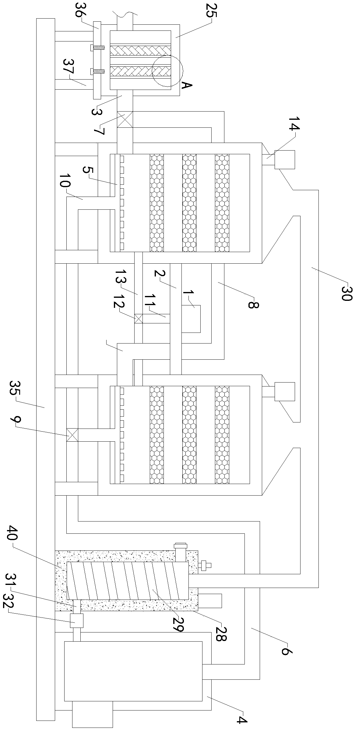
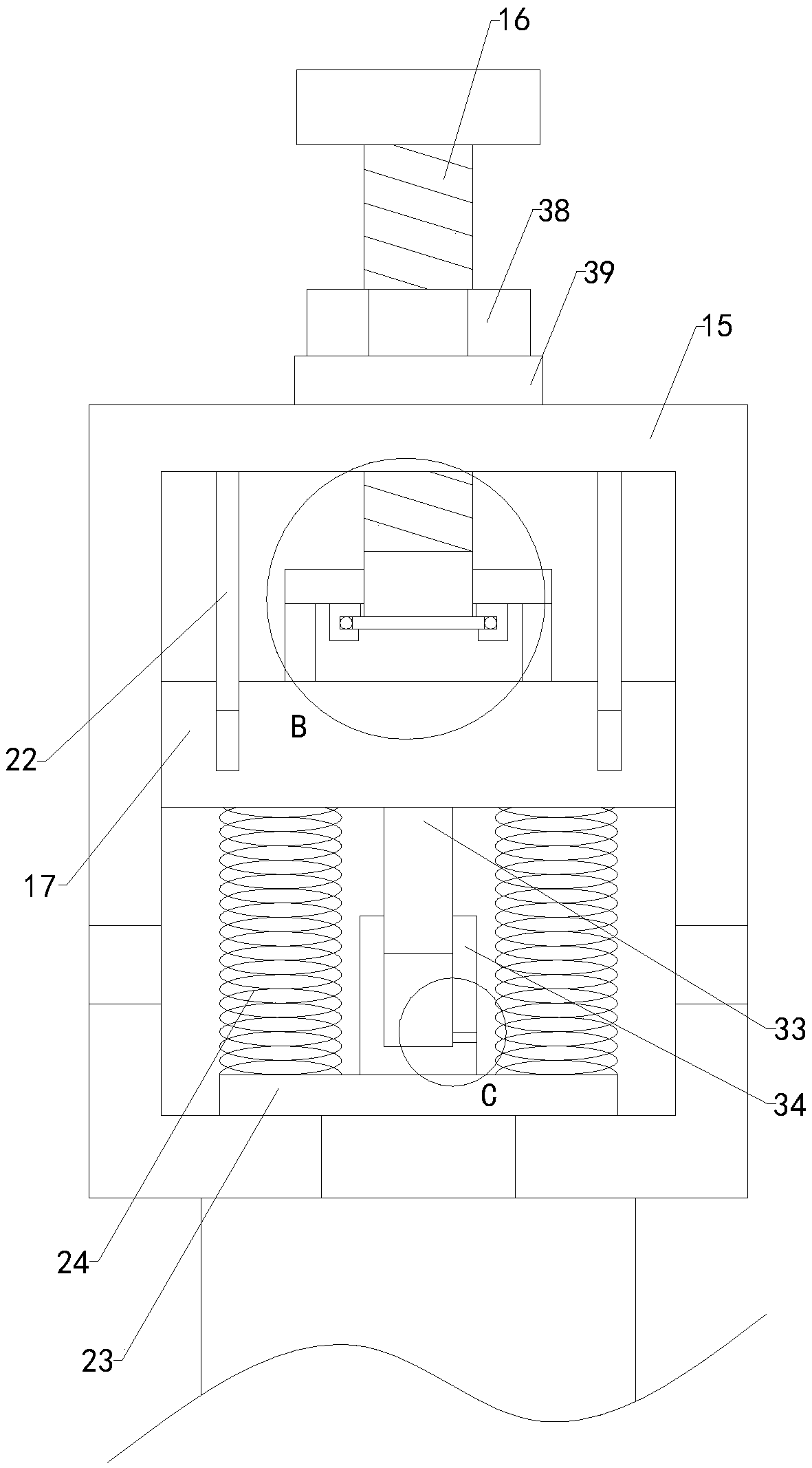
[0022] Such as Figure 1 to Figure 5 As shown, a kind of paint spray waste gas adsorption treatment device of the present invention comprises hot air blower 1, connecting plate 2, first connecting pipe 3, boiler 4, two groups of steam spray discs 5 and first steam pipeline 6, and adsorption tank is provided with two group, and the two groups of adsorption tanks are equipped with adsorption chambers, and the two groups of adsorption chambers are equipped with multiple sets of support screen frames horizontally, and the multiple sets of support screen frames inside the two groups of adsorption chambers are filled with multiple sets of activated carbon Adsorbent, the left fr...


PUM


Abstract

The invention relates to the technical field of accessory device for spraying paint exhaust gas treatment, and in particular, relates to a spraying paint exhaust gas adsorption treatment device. Whenan activated carbon adsorbent is saturated by adsorption, the activated carbon adsorbent can be desorbed and recycled, an adsorption tank has no need to be disassembled to replace the activated carbonadsorbent, and thus the use limitations are reduced; at the same time, the take-off pressure of a relief valve can be adjusted according to the actual situation, so that the pressure inside an adsorption chamber can be maintained constant well, and the flexibility can be improved; moreover, exhaust gas entering the interior of the adsorption chamber can be pretreated, so that large particles arereduced to directly enter the interior of the adsorption chamber, the treatment burden of the activated carbon adsorbent is reduced, and the use reliability is improved. The spraying paint exhaust gasadsorption treatment device includes a hot blower, a connecting plate, a first connecting pipe, a boiler, two groups of steam spray disks, a first steam pipeline, two groups of gas relief pipes, a valve body, an adjusting lead screw, a sealing slide plate, a rotating shaft, a rotating disk, four groups of supporting rods, an adjusting plate, a left limit rod, a right limit rod, a pressure regulating plate, four groups of supporting springs, a pretreatment box and multiple groups of initial effect filter plates.

Description

technical field [0001] The invention relates to the technical field of an accessory device for treating paint spray waste gas, in particular to a paint spray waste gas adsorption treatment device. Background technique [0002] As we all know, the spray paint waste gas adsorption treatment device is an auxiliary device used to absorb and treat the waste gas generated during the painting process of workpieces and automobiles, so as to better reduce environmental pollution. It has been obtained in the field of paint spray waste gas treatment and environmental protection. It has been widely used; the existing spray paint waste gas adsorption treatment device includes an adsorption tank, an adsorption chamber is arranged inside the adsorption tank, and multiple groups of support screen frames are arranged horizontally inside the adsorption chamber, and multiple groups of support screen frames are filled with multiple A group of activated carbon adsorbents, the left front side, le...

Claims


Application Information

Patent Timeline
Patent Type & Authority Applications(China)
IPC IPC(8): B01D53/04B01D46/12B01D46/52
CPCB01D53/0407B01D46/12B01D46/521B01D2253/102B01D2258/0258B01D2259/4009
Inventor 吕海波宋友高
Owner JIANGSU SELF ENVIRONMENTAL SCI & TECHCO
Why Eureka
Try Eureka