
A network time protocol conversion method and system

A technology of network time protocol and conversion method, applied in the field of network time protocol conversion method and system, can solve the problems of complex realization mechanism of high-precision NTP server, acquisition and processing of sending time stamps, increased user investment, etc., to improve NTP time synchronization Accuracy, optimizing and simplifying system design, reducing the effect of adverse factors

Active Publication Date: 2019-10-11
电信科学技术第五研究所有限公司
View PDF4 Cites 0 Cited by
  • Summary
  • Abstract
  • Description
  • Claims
  • Application Information

AI Technical Summary

Problems solved by technology

[0014] 2. The implementation mechanism of high-precision NTP server is complex
[0015] The high-precision NTP server adopts the hardware time stamp mechanism, learns from the PTP synchronization idea, and obtains the data message receiving and sending time stamp (hardware time stamp) at the physical layer. FPGA technology is usually used to realize NTP data message identification, time stamp extraction and insertion, CRC verification and other functions, the implementation mechanism is relatively complex, and the protocol integrity is weak
In addition, NTP does not have a two-step working mode similar to PTP, so it is impossible to obtain and process the sending timestamp through the cooperation of software and hardware. If the MD5 algorithm is considered, the implementation mechanism is more complicated
[0016] 3. The PTP synchronization mechanism has high requirements on the slave clock
For computer high-precision time synchronization applications in the LAN, if the PTP hardware time stamp synchronization mechanism is used, it is necessary to add a PTP slave clock board to realize the hardware time stamp and PTP protocol stack functions, which will undoubtedly increase user investment

Method used


Image

  • A network time protocol conversion method and system
  • A network time protocol conversion method and system
  • A network time protocol conversion method and system

Examples


Embodiment Construction

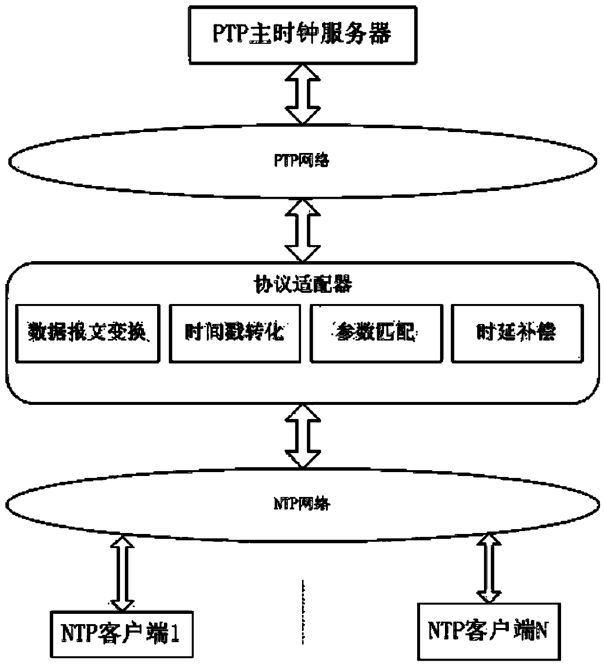
[0044] The present invention will be further described below in conjunction with the accompanying drawings.

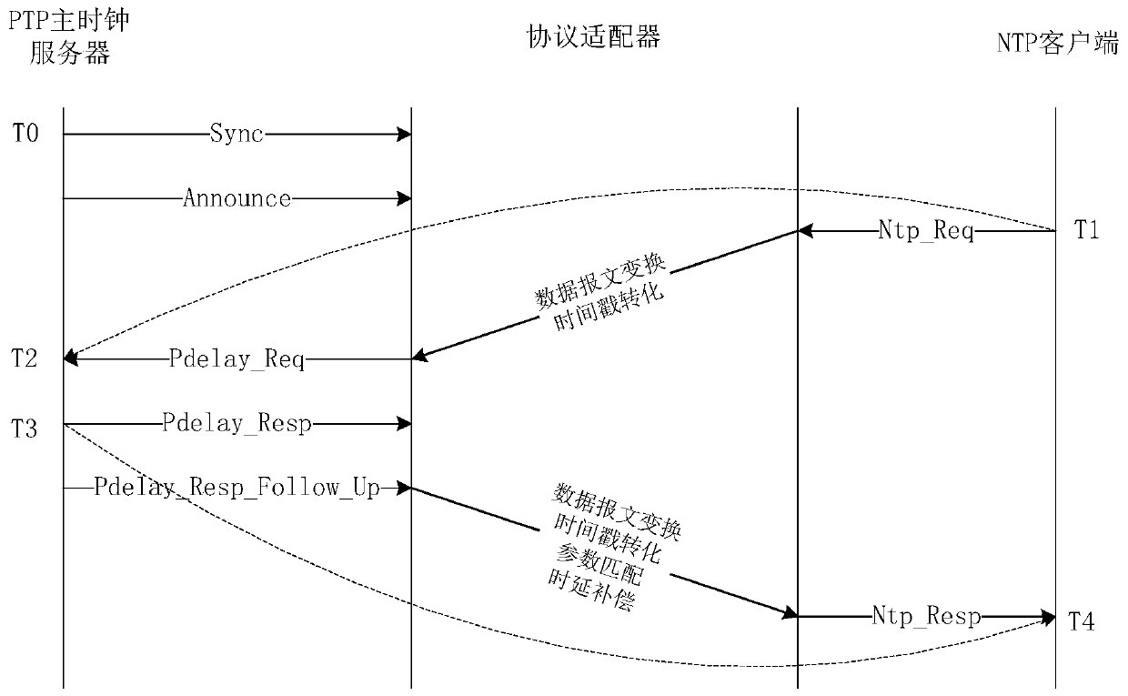
[0045] Such as figure 2 As shown, a network time protocol conversion method specifically includes the following process:

[0046] Step 1, the NTP client sends a time synchronization request message to the protocol adapter;

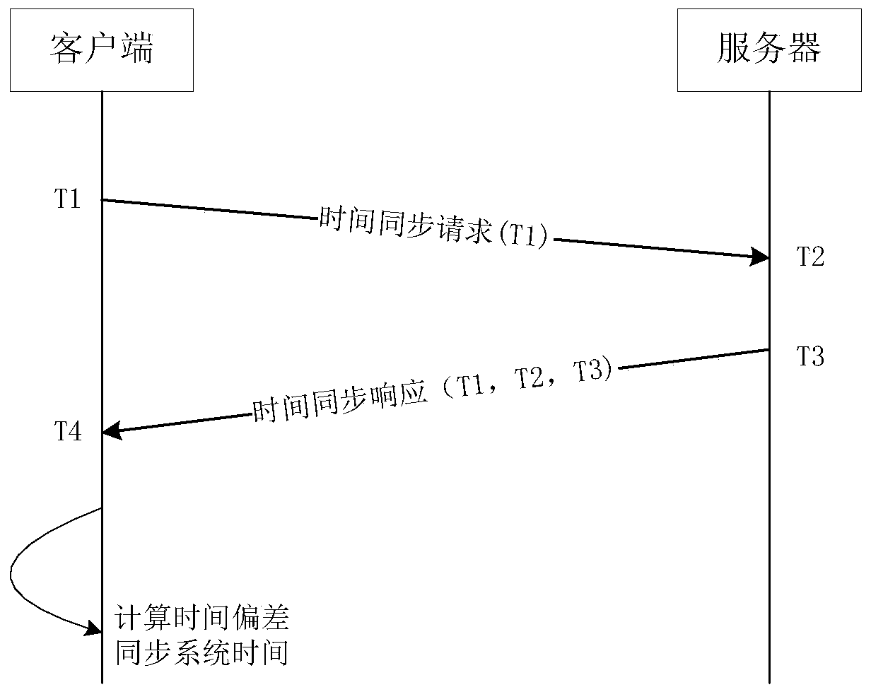
[0047] Preferably, in the step 1, the NTP client sends a time synchronization request message to the protocol adapter through the NTP network, the time synchronization request message (Ntp_Req message) frame format conforms to the standard protocol, and the NTP client adopts C / S (client / server) working mode, the time synchronization request message carries a message sending timestamp T1, and the NTP client can support the MD5 digest algorithm.

[0048] Step 2, the protocol adapter converts the synchronization request message into a delay request message (Pdelay_Req message), and sends the delay request message to the PTP master clock server;

...


PUM


Abstract

The invention relates to time synchronization technical field, and discloses a conversion method of network time protocol, the method provided by the invention specifically comprises the process: NTPclient sends the time synchronization request datagram to protocol adapter, which then transforms the synchronization request datagram to time delay request datagram, and then send the time delay request datagram to a PTP main clock server, the PTP main clock server will produce response datagram and transfer the response datagram to the protocol adapter, which converts the response datagram to NTP time synchronization response datagram and sends the NTP time synchronization response datagram to NTP client, after receiving time synchronization response datagram, the NTP time synchronization response datagram is analyzed by the NTP to achieve time synchronization. NTP time synchronization precision is enhanced through the above mentioned technical scheme, and the demand on network time synchronization precision is met by combining with the features of PTP and NTP, the synchronization precision can be guaranteed, the deploy is simple, the invention also discloses a network time protocolconversion system.

Description

technical field [0001] The invention relates to the technical field of time synchronization, in particular to a network time protocol conversion method and system. Background technique [0002] PTP and NTP are currently the most widely used network time protocols for time synchronization between computers or devices in the network. [0003] PTP is a precision time protocol, a precision time protocol standard for network measurement and control systems formulated by IEEE, also known as IEEE 1588, which has been developed to IEEE 1588v2 version. PTP adopts the master-slave synchronization method and defines three clock models, including ordinary clock (OC), boundary clock (BC) and transparent clock (TC), among which BC has the function of master-slave clock at the same time; Delay measurement mechanism, the P2P delay mechanism is used for point-to-point delay measurement, emphasizing the delay measurement between two adjacent nodes, which helps to eliminate the influence of l...

Claims


Application Information

Patent Timeline
Patent Type & Authority Patents(China)
IPC IPC(8): H04L29/06H04J3/06
Inventor 王广才何定高王茂凌邓皓胥骥
Owner 电信科学技术第五研究所有限公司
Learn More