
Self-adaptive radiation unit with multiple phase centers and array antenna

A radiation unit and array antenna technology, applied in the field of array antennas, can solve the problems of unavoidable control circuits, large antenna size, and no antenna unit

Active Publication Date: 2018-10-16
UNIV OF SCI & TECH OF CHINA
View PDF5 Cites 6 Cited by
  • Summary
  • Abstract
  • Description
  • Claims
  • Application Information

AI Technical Summary

Problems solved by technology

But this switch-based design still inevitably complicates the control circuit
[0007] The above literature shows that the current beam deflection antenna based on the mechanically rotating radiating unit is constrained by the mechanical rotation rate and inertia, and the unit beam reconfigurable antenna based on the microwave switch requires complex control circuits to control the on-off of each switch, and Since the main principle of reconfigurability is to use different parts of the antenna unit for radiation, there is a problem of large antenna size
[0008] At present, there is no report on the design of an antenna unit that can be used for large-angle scanning without increasing the complexity of the original structure of the planar array antenna, that is, without using additional structures

Method used


Image

  • Self-adaptive radiation unit with multiple phase centers and array antenna
  • Self-adaptive radiation unit with multiple phase centers and array antenna
  • Self-adaptive radiation unit with multiple phase centers and array antenna

Examples


Embodiment Construction

[0026] The embodiments of the present invention will be further described in detail below. The content not described in detail in the embodiments of the present invention belongs to the prior art known to those skilled in the art.

[0027] The adaptive radiating unit and array antenna with multi-phase center of the present invention, its preferred embodiment is:

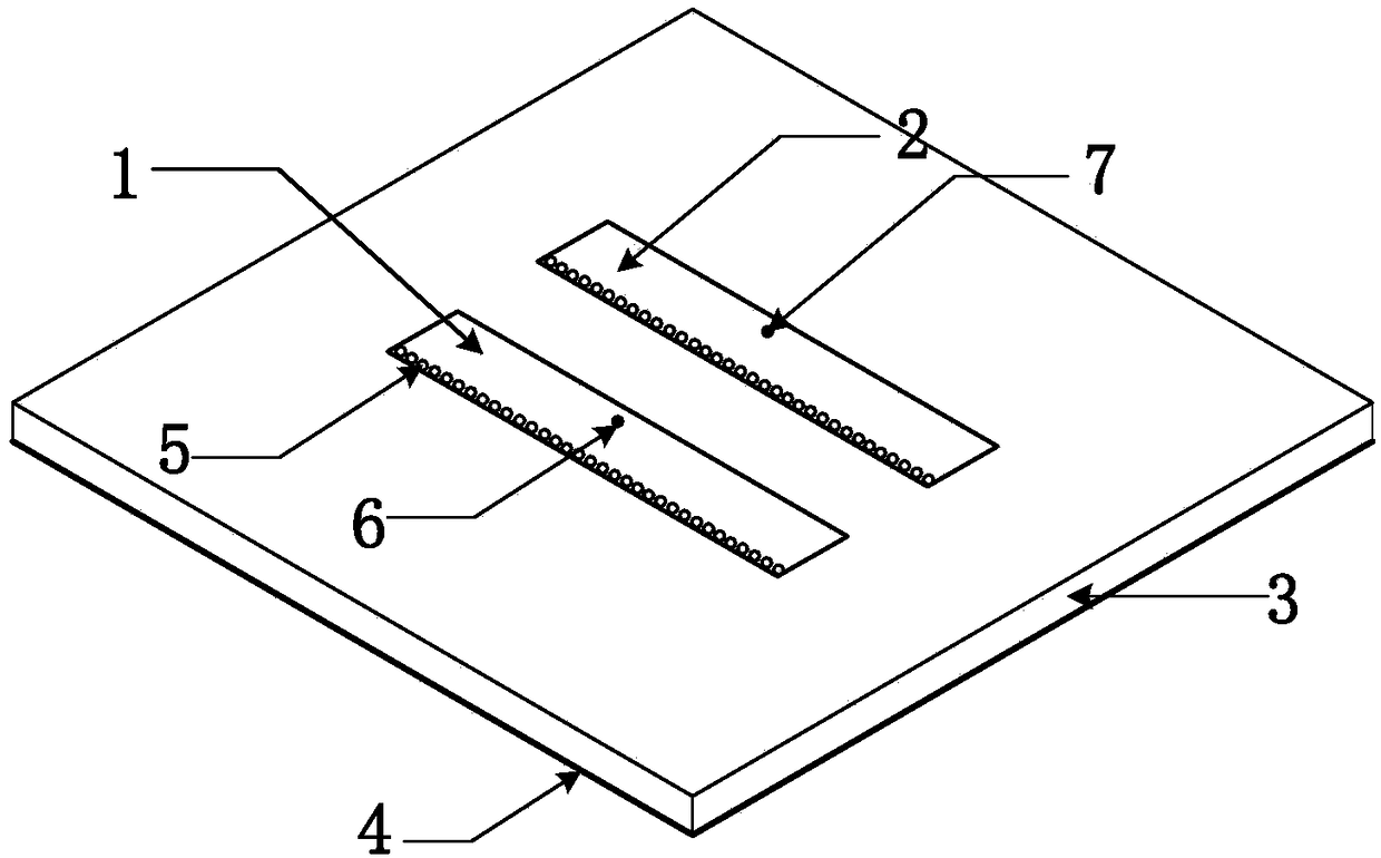
[0028] The self-adaptive radiating unit with a multi-phase center includes a dielectric substrate, a metal layer on its lower surface, and a printed circuit on its upper surface. The hole is connected to the metal layer on the lower surface, and the two rectangular metal patches are respectively connected to a feed port, and the feed port is connected to a phase shifter;

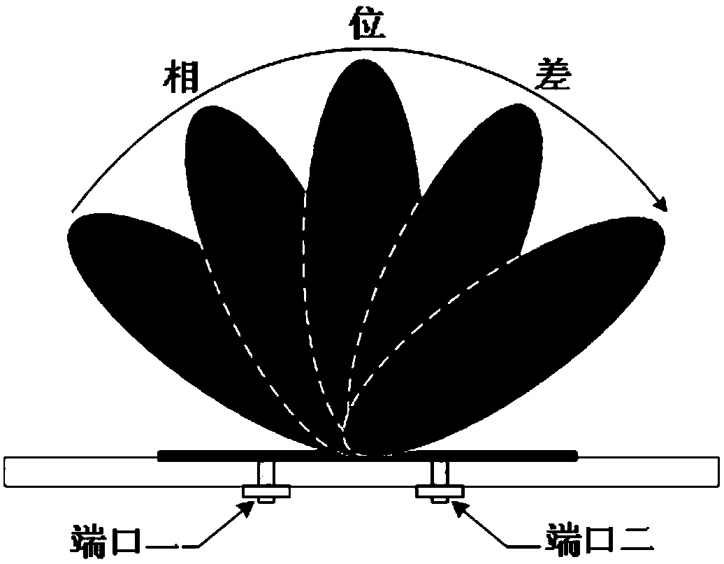
[0029] The adaptive radiating unit has multiple phase centers, and the feeding phase of each phase center is variable, and the radiation pattern of the adaptive radiating unit is changed by changing the phase relationship between the phase centers...


PUM

PropertyMeasurementUnit
Thicknessaaaaaaaaaa
Thicknessaaaaaaaaaa
Center distanceaaaaaaaaaa

Abstract

The invention discloses a self-adaptive radiation unit with multiple phase centers and an array antenna. The self-adaptive radiation unit comprises a dielectric substrate and two rectangular metal patches of a lower surface metal layer and an upper surface printing circuit, wherein the two rectangular metal patches are connected with the lower surface metal layer via grounding metal through holesand are connected with a feeding port, the feeding port is connected with a phase shifter, the self-adaptive radiation unit is provided with multiple phase centers, a feeding phase of each phase center is variable, and a radiation direction diagram of the self-adaptive radiation unit is changed by changing a phase relation among the phase centers. A plurality of self-adaptive radiation units of the array antenna are connected, adjacent ports of adjacent self-adaptive radiation units share the phase shifter, the pointing direction of a unit directional diagram points is automatically deflectedwith an array factor, and the deflection of a unit wave beam with an array scanning angle and large-angle scanning of the array are achieved under the condition that the number of the phase shifters of a traditional array antenna is not increased and the complexity of a feeding is not improved.

Description

technical field [0001] The invention relates to an array antenna technology for realizing large-angle scanning, in particular to an adaptive radiation unit with multiple phase centers and an array antenna. Background technique [0002] The beam scanning range of the phased array antenna is an important indicator of the phased array antenna, and for the traditional planar phased array antenna, due to the reduction of the projected area of ​​the array aperture and the influence of the mismatch of the active impedance of the unit when scanning at a large angle, Its effective scanning angle usually does not exceed ±40° (Mailloux R.J., Phased Array Antenna Handbook, Artech House, 1994.). The scanning angle of the planar phased array antenna limits its application range. [0003] In recent years, scholars at home and abroad have conducted a series of studies on expanding the scanning range of beam scanning arrays. One of the ideas is to increase the gain of the unit at low elevat...

Claims


Application Information

Patent Timeline
IPC IPC(8): H01Q21/00H01Q1/48H01Q1/50H01Q1/38H01Q3/26H01Q3/30
CPCH01Q1/38H01Q1/48H01Q1/50H01Q3/2605H01Q3/30H01Q21/0006
Inventor 朱旗王亚宁
Owner UNIV OF SCI & TECH OF CHINA
Learn More